Method, device and system for detecting leakage of storage tank

A technology of storage tank and position information, applied in measuring devices, by detecting the appearance of fluid at the leak point, testing the fluid tightness, etc., it can solve the problem of lack of detection capability of the center of the tank bottom, difficult to meet explosion-proof requirements, and detection signals. Large attenuation and other problems, to achieve the effect of reducing hidden dangers in detection, avoiding excessive maintenance and economic waste, and improving reliability

Active Publication Date: 2021-05-11
CHINA PETROLEUM & CHEM CORP +1
View PDF11 Cites 0 Cited by
  • Summary
  • Abstract
  • Description
  • Claims
  • Application Information

AI Technical Summary

Problems solved by technology

Among them, the online detection technology of storage tank robots has a high degree of automation and high detection efficiency, but it is not suitable for the detection of crude oil storage tanks with thick sediment layers and complex heaters; the online detection of guided waves on the bottom plate of storage tanks is not affected by the liquid in the tank. impact, but the detection signal attenuation is large and lacks the ability to detect the center of the tank bottom; the acoustic emission method uses the elastic wave signal sent out when the storage tank is corroded and leaked for damage judgment, without stopping production and opening the tank, and properly arranging sensors outside the tank Realize the monitoring of storage tanks, real-time, dynamic and online detection and evaluation of corrosion and leakage of the storage tank bottom plate, but still limited by the attenuation of the signal and lack the ability to detect the center of the tank bottom
More importantly, the medium of the storage tank is flammable and explosive, and the requirements for the explosion-proof safety level of the online detection method are very high, and these detection systems are often difficult to meet the explosion-proof requirements

Method used


Image

  • Method, device and system for detecting leakage of storage tank
  • Method, device and system for detecting leakage of storage tank
  • Method, device and system for detecting leakage of storage tank

Examples


Embodiment 1

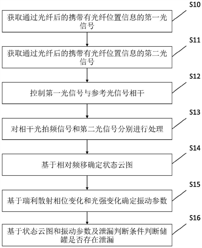
[0034] figure 1It is a flow chart of the method for detecting the leakage of the storage tank provided by Embodiment 1 of the present invention. Wherein, the surface of the storage tank is arranged with optical fibers and the optical fibers are sensitive to temperature but insensitive to strain. Wherein, the manner of arranging the optical fiber on the surface of the storage tank may depend on specific conditions. For example, for a new storage tank, the optical fiber can be arranged on the surface of the storage tank in the following way: on the lower surface of the storage tank floor, starting from the center of the tank bottom, laying concentric rings to the edge of the tank bottom, and winding from the inlet and outlet After 2 turns, it is connected to the outer wall of the bottom plate of the storage tank, and the optical fiber is laid on the outer wall of the storage tank in a circular parallel winding manner at a distance of 1m to the highest liquid level of the storag...

Embodiment 2

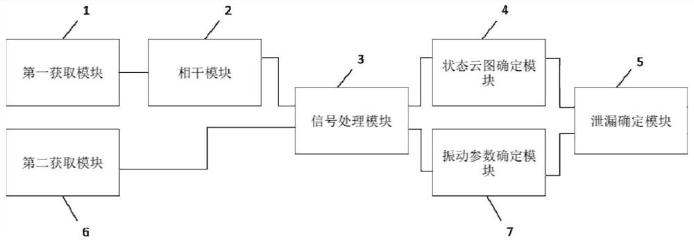
[0048] figure 2 It is a structural block diagram of the device for detecting storage tank leakage provided by Embodiment 2 of the present invention. like figure 2 As shown, the device includes a first acquisition module 1 , a second acquisition module 6 , a coherence module 2 , a signal processing module 3 , a state nephogram determination module 4 , a vibration parameter determination module 7 and a leakage determination module 5 . Wherein, the first acquisition module 1 is used to acquire the first optical signal carrying the position information of the optical fiber after passing through the optical fiber, wherein the first optical signal includes backward Stokes light generated based on the Brillouin scattering effect; The second acquisition module 6 is used to acquire the second optical signal carrying the position information of the optical fiber after passing through the optical fiber, wherein the second optical signal includes Rayleigh scattered light generated base...

Embodiment 3

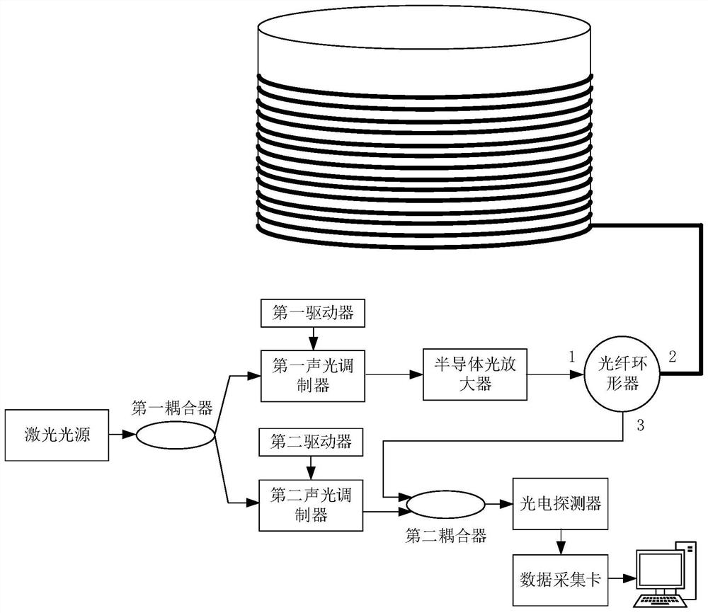
[0058] Combine below image 3 and Figure 4 The system for detecting leakage of a storage tank provided in the embodiment of the present invention is explained, wherein the content explained can also be used to explain the method and device for detecting leakage of a storage tank in the above embodiments.


PUM


Abstract

The embodiment of the invention provides a method, device and system for detecting leakage of a storage tank, and belongs to the technical field of storage tank safety detection. The method comprises the following steps of acquiring a first optical signal carrying the optical fiber position information after passing through an optical fiber; acquiring a second optical signal carrying the optical fiber position information after passing through the optical fiber; controlling the first optical signal to be coherent with a reference optical signal to obtain a coherent optical beat frequency signal; respectively processing the coherent light beat frequency signal and the second light signal to obtain a relative frequency shift corresponding to the coherent light beat frequency signal and a Rayleigh scattering phase change and a light intensity change corresponding to the second light signal; determining a state cloud picture based on the relative frequency shift; determining a vibration parameter based on the Rayleigh scattering phase change and the light intensity change; and judging whether the storage tank leaks or not based on the state cloud picture, the vibration parameters and leakage judgment conditions.

Description

technical field [0001] The invention relates to the technical field of storage tank safety detection, in particular to a method, device and system for detecting leakage of a storage tank. Background technique [0002] With the continuous and rapid development of my country's economy, the scale of petroleum processing and hazardous chemical production continues to expand, and the storage capacity of related raw materials, intermediate products and finished products continues to increase. Storage tanks are an important type of storage container structure. There are nearly 10,000 tanks, and more than 10,000 storage tanks in the refining and chemical industry. At the same time, in order to avoid national security risks brought about by energy supply, my country has built 9 national oil reserve bases including Zhoushan, Zhenhai, Dalian, and Huangdao. 100,000 square storage tanks have become the mainstream. It is estimated that before 2020, the country will add nearly 1,000 storag...

Claims


Application Information

Patent Timeline
Patent Type & Authority Applications(China)
IPC IPC(8): G01M3/38G01M3/00G01M3/24
CPCG01M3/38G01M3/002G01M3/24
Inventor 邱枫屈定荣李明骏白永忠韩磊张艳玲
Owner CHINA PETROLEUM & CHEM CORP
Why Eureka
Try Eureka