Copper ingot punching equipment for metal machining

A punching equipment and metal processing technology, applied in metal processing equipment, metal processing, drilling/drilling equipment, etc., can solve the problems of low work efficiency, waste of resources, low safety, etc., and achieve high work efficiency and protection The effect of high safety and automation technology

Pending Publication Date: 2021-05-14
View PDF6 Cites 10 Cited by
  • Summary
  • Abstract
  • Description
  • Claims
  • Application Information

AI Technical Summary

Problems solved by technology

[0004] In order to overcome the shortcomings of low work efficiency, low safety, and waste of resources, the technical problem to be solved is: to provide a method that does not require people to manually place copper ingots, has high automation technology, and can better fix copper ingots. Copper ingot drilling equipment for metal processing

Method used


Image

  • Copper ingot punching equipment for metal machining
  • Copper ingot punching equipment for metal machining
  • Copper ingot punching equipment for metal machining

Examples


Embodiment 1

[0087] A copper ingot punching equipment for metal processing, such as Figure 1-3 As shown, it includes a base 1, a tripod 2, a drilling mechanism 3 and an installation device 4. The top of the base 1 is symmetrically provided with a tripod 2, the left side of the top of the base 1 is provided with an installation device 4, and the front side of the installation device 4 is provided with Drilling mechanism 3.

[0088] When people need to punch copper ingots for metal processing, they can use this device. First, place the support tool on the left side of the base 1, then place the copper ingot on the support tool, and then open the drilling mechanism 3 , and then the drilling mechanism 3 just punches the copper ingot, so that the copper ingot punching is completed, as no longer need to use this equipment, the drilling mechanism 3 can be closed.

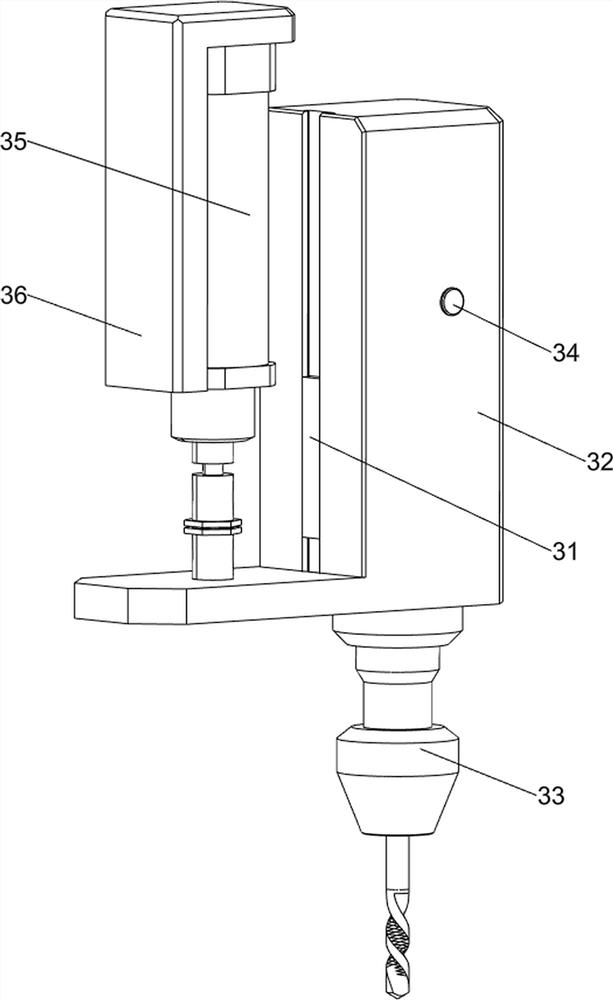
[0089] Drilling mechanism 3 includes fixed guide rail 31, sliding frame 32, electric drill 33, first fixed pin 34, cylinder 35 and ...

Embodiment 2

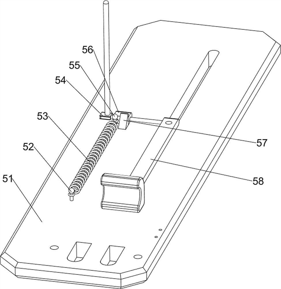
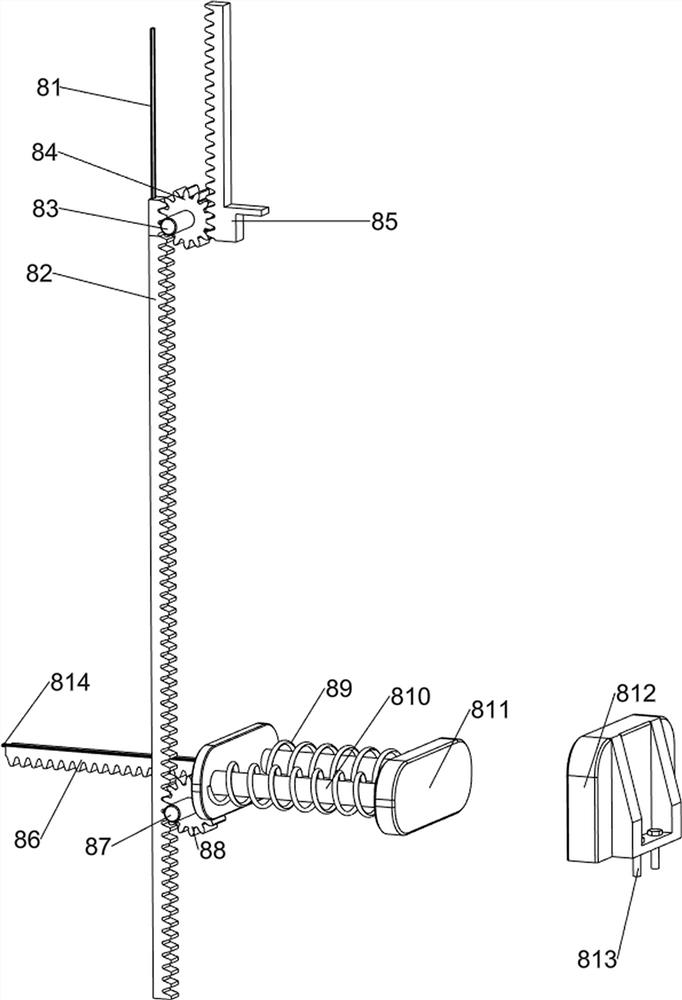
[0094] On the basis of Example 1, such as figure 1 and Figure 4-8 As shown, a feed mechanism 5 is also included, and the feed mechanism 5 includes a panel 51, a first fixed column 52, a first spring 53, a connecting rod 54, a second fixed column 55, a pull hook 56, a limit tooth 57 and a push material Rod 58, the tripod 2 is provided with a panel 51, the left side of the top of the panel 51 is provided with a first fixed column 52, the top of the panel 51 is slidingly equipped with a pusher rod 58, and the rear side of the pusher rod 58 is provided with a connecting rod 54. The rod 54 is provided with a pull hook 56, the left side of the pull hook 56 is provided with a second fixed column 55, and a first spring 53 is arranged between the second fixed column 55 and the first fixed column 52, and the pull hook 56 contacts with the panel 51, and the left side of the pull hook 56 Limiting teeth 57 are provided on the side.

[0095] When the telescopic rod of the cylinder 35 mov...


PUM


Abstract

The invention relates to punching equipment, in particular to copper ingot punching equipment for metal machining. A technical problem needs to be solved to provide the copper ingot punching equipment for metal machining, so that people do not need to place a copper ingot manually, the automation degree is high, and the copper ingots can be better fixed. The copper ingot punching equipment for metal machining comprises a base, a mounting device and drilling mechanism, wherein foot stools are symmetrically arranged on the base, the mounting device is arranged on the base, and the drilling mechanism is arranged on the mounting device. According to the copper ingot punching equipment for metal machining, the drilling mechanism is arranged, an air cylinder is started to drive an electric drill to move downwards, and at the moment, the copper ingot can be automatically punched, so that the effects of being high in punching efficiency and capable of punching for a long time are achieved.

Description

technical field [0001] The invention relates to a punching device, in particular to a copper ingot punching device for metal processing. Background technique [0002] Metal processing is the production activity of applying various processes to metal materials to manufacture required parts, production line components or overall large-scale structures. The process of metal processing can be roughly divided into three categories, namely metal forming, metal cutting and metal connection. Drilling holes on metal parts is the most common example of metal chipping process, but in traditional drilling equipment, people need to manually place copper ingots, which has a high risk factor and is likely to cause danger, and then work The efficiency is slow, and sometimes the copper ingots cannot be drilled well, which will waste resources. [0003] To sum up, in view of the above existing problems, a copper ingot punching equipment for metal processing is designed that does not require ...

Claims


Application Information

Patent Timeline
Patent Type & Authority Applications(China)
IPC IPC(8): B23B41/00B23Q7/00
CPCB23B41/00B23Q7/00
Inventor 廖斯靖
Why Eureka
Try Eureka