
Sulfur purification system and purification process thereof

A sulfur and liquid sulfur technology, applied in the preparation/purification of sulfur, sulfur compounds, inorganic chemistry, etc., can solve the problems of long process route, high energy consumption, flammability and explosion, and achieve simple process, high safety, high efficiency effect

Pending Publication Date: 2021-05-14
王占华
View PDF0 Cites 0 Cited by
  • Summary
  • Abstract
  • Description
  • Claims
  • Application Information

AI Technical Summary

Problems solved by technology

Sulfur purification has used methods such as melting, vaporization and vacuum distillation; but these methods have the disadvantages of long process route, incomplete separation of organic matter, high energy consumption and unstable product quality, so they have not been industrialized
[0004] Organic solvents are used to extract sulfur in crude sulfur, and the organic solvents with good sulfur solubility are mainly used, such as CS 2 (carbon disulfide), C 2 HCl 3 (Trichlorethylene), etc.; by pulverizing the crude sulfur and mixing it with the organic solvent used in proportion, dissolving the sulfur into the solvent at a certain temperature, then filtering out the insoluble impurities, and then cooling the remaining solution to a certain temperature temperature, the sulfur dissolved in the solvent will crystallize, and the qualified sulfur with high purity can be obtained after the sulfur crystallization is reprocessed; because the organic solvent is harmful to the human body and has flammable and explosive characteristics, the safety production requirements are very high ; In the production process, because the volatile characteristics of the organic solvent consume part of the organic solvent, therefore, the production cost of this extraction process is relatively high

Method used


Image

  • Sulfur purification system and purification process thereof

Examples


Embodiment Construction

[0037] Below, the present invention will be further described in conjunction with the accompanying drawings and specific embodiments.

[0038] In order to illustrate the technical solutions of the embodiments of the present invention more clearly, the accompanying drawings of the embodiments will be briefly introduced below. Obviously, the accompanying drawings in the following description are only some embodiments of the present invention, and those of ordinary skill in the art Generally speaking, other drawings can also be obtained based on these drawings on the premise of not paying creative work.

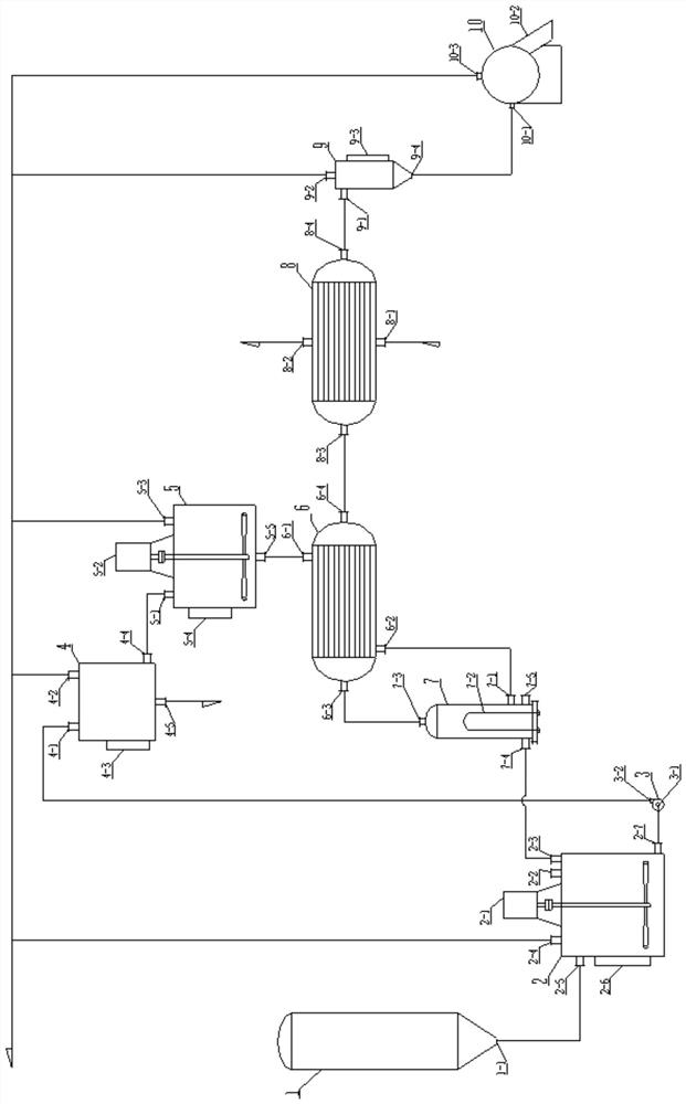
[0039] see as figure 1 As shown, including sulfur melting tank, stirring tank, liquid sulfur pump, separation device, decomposition tank, gas-liquid heat exchanger, heater, cooler, separator and slicer;

[0040] Sulfur melting tank, stirring tank, separation device and decomposition tank are connected in sequence;

[0041] One end of the connecting pipe between the sulfur melt...


PUM


Abstract

The invention discloses a sulfur purification system and a sulfur purification process, and belongs to the technical field of sulfur purification. Liquid crude sulfur melted by the sulfur melting kettle is discharged into the stirring tank and pumped by the liquid sulfur pump to be conveyed to the separation device, the crude sulfur after solid impurities are separated enters the decomposition tank to be heated, liquid sulfur discharged from the decomposition tank enters the outside of a pipe of the gas-liquid heat exchanger to exchange heat with gaseous sulfur in the pipe, and the liquid sulfur is discharged out of the gas-liquid heat exchanger to enter the heater; liquid sulfur in the heater is heated to the boiling point temperature to be gasified, gaseous sulfur enters a pipe of a gas-liquid heat exchanger from the heater and exchanges heat with liquid sulfur outside the pipe, and gas-liquid mixed sulfur after gas-liquid heat exchanger enters a pipe of a cooler and exchanges heat with a medium outside the pipe; and the sulfur discharged from the cooler is in a liquid state and enters a slicing machine through a separator to prepare refined sulfur slices. The method not only has better safety, but also is high in efficiency, and the adopted purification process is simple.

Description

technical field [0001] The invention relates to the technical field of sulfur purification, in particular to a sulfur purification system and a purification process thereof. Background technique [0002] my country's sulfur minerals are very poor, and the pure sulfur necessary for industries such as sulfuric acid, rubber, and compound fertilizers mainly relies on imports. Due to the rich coal resources in our country, there are many coal chemical plants (including chemical fertilizers, coking, methanol, coal-to-oil plants, etc.) The amount is small and scattered, but the total output of crude sulfur in the country is huge, and its sulfur content is mostly between 80-98%, with high impurity content and various impurity components, which are not easily accepted by industries such as sulfuric acid, rubber, and compound fertilizer. , failed to be effectively utilized and disposed of, and could easily cause serious environmental pollution and potential safety hazards during the ...

Claims


Application Information

Patent Timeline
IPC IPC(8): C01B17/02
CPCC01B17/0232
Inventor 王占华
Owner 王占华
Learn More