Sludge drying device

A sludge drying and drying technology, applied in dewatering/drying/concentrating sludge treatment, transportation and packaging, chemical instruments and methods, etc., can solve the problem of uneven drying, poor drying effect and low drying efficiency and other problems, to achieve the effect of good drying effect, fast replacement speed and high drying efficiency

Active Publication Date: 2021-05-14
ZHEJIANG SANLIAN ENVIRONMENT MACHINERY EQUIP
View PDF9 Cites 3 Cited by
  • Summary
  • Abstract
  • Description
  • Claims
  • Application Information

AI Technical Summary

Problems solved by technology

[0003] The present invention aims to overcome the above-mentioned problems of low drying efficiency, poor drying effect, uneven drying, and large wear and tear during the installation process that will affect the service life of the drying equipment in the existing drying device, and provides a sludge Drying device, high-temperature hot flue gas is directly dried, with high heat transfer efficiency and good drying effect; fast specific surface area replacement speed and high drying efficiency; drying is carried out by Brownian motion, and the drying is uniform; reducing equipment wear and improving equipment service life; Reduce mechanical energy consumption

Method used


Image

  • Sludge drying device
  • Sludge drying device
  • Sludge drying device

Examples


Embodiment 1

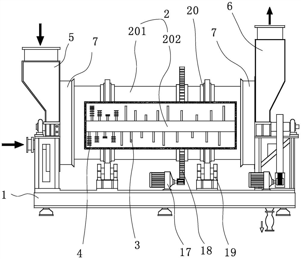
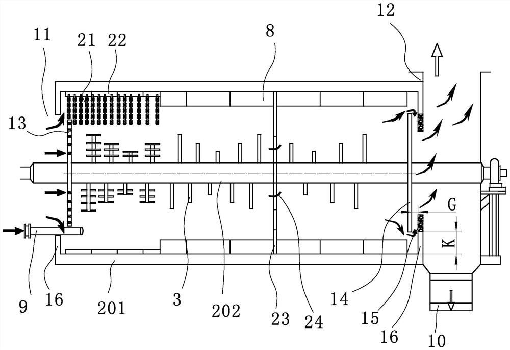
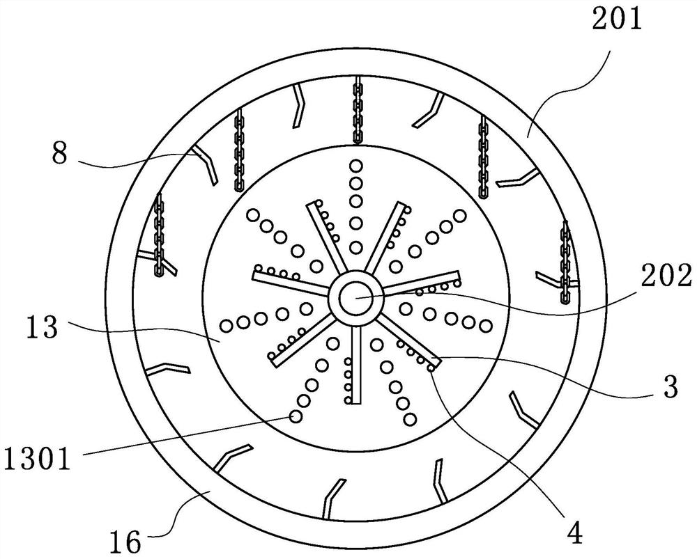
[0026] Such as figure 1 , figure 2 In the shown embodiment 1, a sludge drying device includes a drying drum 2. The drying drum 2 includes a horizontally arranged outer drum 201 and an inner rotor 202 arranged inside the outer drum 201. The drum 201 and the inner rotor 202 are in the same direction, and the inner rotor 202 is provided with a number of stirring rods 3 arranged in a double helix shape, and an auxiliary crushing structure is arranged on the inner wall of the outer drum 201 to dry the drum. 2 The two ends are the inlet port 11 and the outlet port 12 respectively. The inlet port 11 is connected to the inlet chamber 5 for receiving hot flue gas, and the outlet port 12 is connected to the outlet chamber 6 for discharging low-temperature hot flue gas. At the inlet port 11 The bottom is also provided with a feed port 9, and a discharge port 10 is provided at the bottom of the outlet end 12. The drying drum 2 is successively divided into a front section, a middle secti...

Embodiment 2

[0035] Such as figure 2 As shown, the technical solution of embodiment 2 is basically the same as the technical solution of embodiment 1, and the difference is that the auxiliary crushing structure includes a chain 22 and a lifting plate 8 arranged on the inner wall surface of the outer drum 201, and in the outer drum 201 The front section of the wall is provided with a chain fixing plate 21, the chain 22 is fixed on the chain fixing plate 21, and the lifting plate 8 is arranged on the outer drum 201 of the middle section and the rear section. In the front section of the drying drum 2, the material is a large piece of wet material, and the setting of the chain 22 is beneficial to prevent the adhesion of the wet material, and at the same time has the function of breaking the wet material, and the chain 22 is detachably connected to the outer drum 201. The disassembly and replacement of the chain 22 is realized, and the thickness of the chain 22 is conveniently determined accor...

Embodiment 3

[0037] The technical solution of embodiment 3 is basically the same as the technical solution of embodiment 1, and the difference is that the stirring rod 3 in the front section is a semi-cylindrical structure, and the plane of the stirring rod 3 faces the side of the inlet end 11, and the semicircular surface faces One side of the outlet port 12. Such setting is beneficial to push the material to move toward the outlet end 12, ensure that the material moves toward the outlet as much as possible, and reduce the probability of the material splashing toward the inlet.


PUM


Abstract

The invention discloses a sludge drying device which comprises a drying rotary drum; the drying rotary drum comprises a horizontally arranged outer rotary drum and an inner rotor arranged in the outer rotary drum, the two ends of the drying rotary drum are an inlet end and an outlet end respectively, the inlet end is connected with a gas inlet chamber used for introducing hot flue gas, and the outlet end is connected with a gas outlet chamber used for discharging low-temperature hot flue gas; the drying rotary drum is sequentially divided into a front section, a middle section and a rear section from the inlet end to the outlet end, the outer rotary drum and the inner rotor rotate in the same direction, a plurality of stirring rods are arranged on the inner rotor, and the stirring rods are arranged in a double-helix shape; and an auxiliary crushing structure is arranged on the inner wall surface of the outer rotary drum. According to the sludge drying device provided by the invention, high-temperature hot flue gas is used for direct drying, the heat transfer efficiency is high, and the drying effect is good; the specific surface area replacement speed is high and the drying efficiency is high; drying is conducted in a Brownian motion mode, and drying is uniform; equipment abrasion is reduced, and the service life of equipment is prolonged; the mechanical energy consumption is reduced.

Description

technical field [0001] The invention relates to the technical field of sludge treatment, in particular to a screw propulsion sludge drying device. Background technique Background technique [0002] With the development of modern industry, a huge amount of various types of urban domestic sludge and industrial sludge are produced around the world every year. Among them, various types of sewage and wastewater treatment plants will produce a large amount of wet sludge with high water content, which needs to be dried before being incinerated in an incinerator or transported for other purposes. The sludge drying technology is A common technology that can effectively reduce the moisture content of sludge so that it can continue to be processed further is the process of heating the sludge in specially designed equipment and evaporating the water in it. It can not only effectively remove the "free water" in the sludge, but also quickly evaporate the "interstitial water", "surface ...

Claims


Application Information

Patent Timeline
Patent Type & Authority Applications(China)
IPC IPC(8): C02F11/13B01F9/08B01F15/06B02C13/06B02C13/28B02C13/30B01F29/64
CPCC02F11/13B02C13/06B02C13/2804B02C13/30B02C2201/06B01F29/64B01F35/91B01F2035/99
Inventor 纪伟勇张家云蓝丽梅
Owner ZHEJIANG SANLIAN ENVIRONMENT MACHINERY EQUIP
Why Eureka
Try Eureka