
Condensation heat recovery system for power plant

A recovery system and condensation heat technology, applied in heat pumps, heat exchange equipment, lighting and heating equipment, etc., can solve the problem of accelerating the corrosion rate of related pipelines and equipment, increasing the supercooling degree of condensed water, and increasing the oxygen content of condensed water and other problems, to achieve the effect of increasing the speed, balancing the cooling effect, and reducing the operation steps

Active Publication Date: 2021-05-14
巢湖市鑫皖新能源有限公司
View PDF5 Cites 0 Cited by
  • Summary
  • Abstract
  • Description
  • Claims
  • Application Information

AI Technical Summary

Problems solved by technology

[0005] In order to make up for the deficiencies of the existing technology, the temperature of the circulating water after the heat recovery of the heat pump is low, which will easily lead to an increase in the supercooling degree of the condensed water, which will lead to an increase in the oxygen content in the condensed water, which will lead to the acceleration of the condensed water during operation. To the problem of the corrosion rate of relevant pipelines and equipment, a kind of power plant condensation heat recovery system proposed by the present invention

Method used


Image

  • Condensation heat recovery system for power plant
  • Condensation heat recovery system for power plant
  • Condensation heat recovery system for power plant

Examples


Embodiment approach

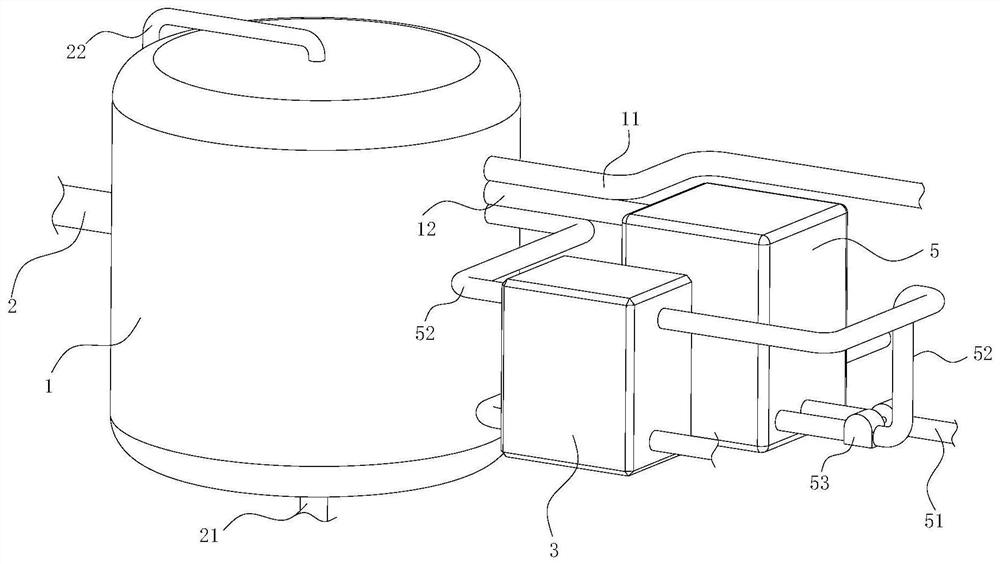
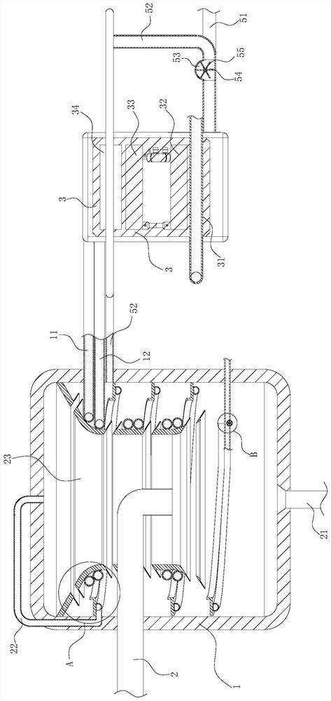
[0026] As an embodiment of the present invention, the water outlet pipe 12 is fixedly connected to the water storage tank 5 on the side close to the heat exchanger 3; Connected with a blowdown pipe 51; the blowdown pipe 51 is used to discharge boiler high-temperature waste water; the blowdown pipe 51 extends into the water storage tank 5; the blowdown pipe 51 is arranged in a spiral shape in the water storage tank 5; during work, the boiler The waste water itself contains high temperature, which causes a large amount of heat loss when it is discharged. At the same time, after the circulating water flows out of the condensation tank 1, the temperature is kept at 30-50°C all the year round. The sewage pipe 51 is extended to the water storage tank 5, and the circulating water and the boiler are used to The large temperature difference between the wastewater can effectively enhance the utilization efficiency of heat, and at the same time, the existence of the water storage tank 5 c...


PUM


Abstract

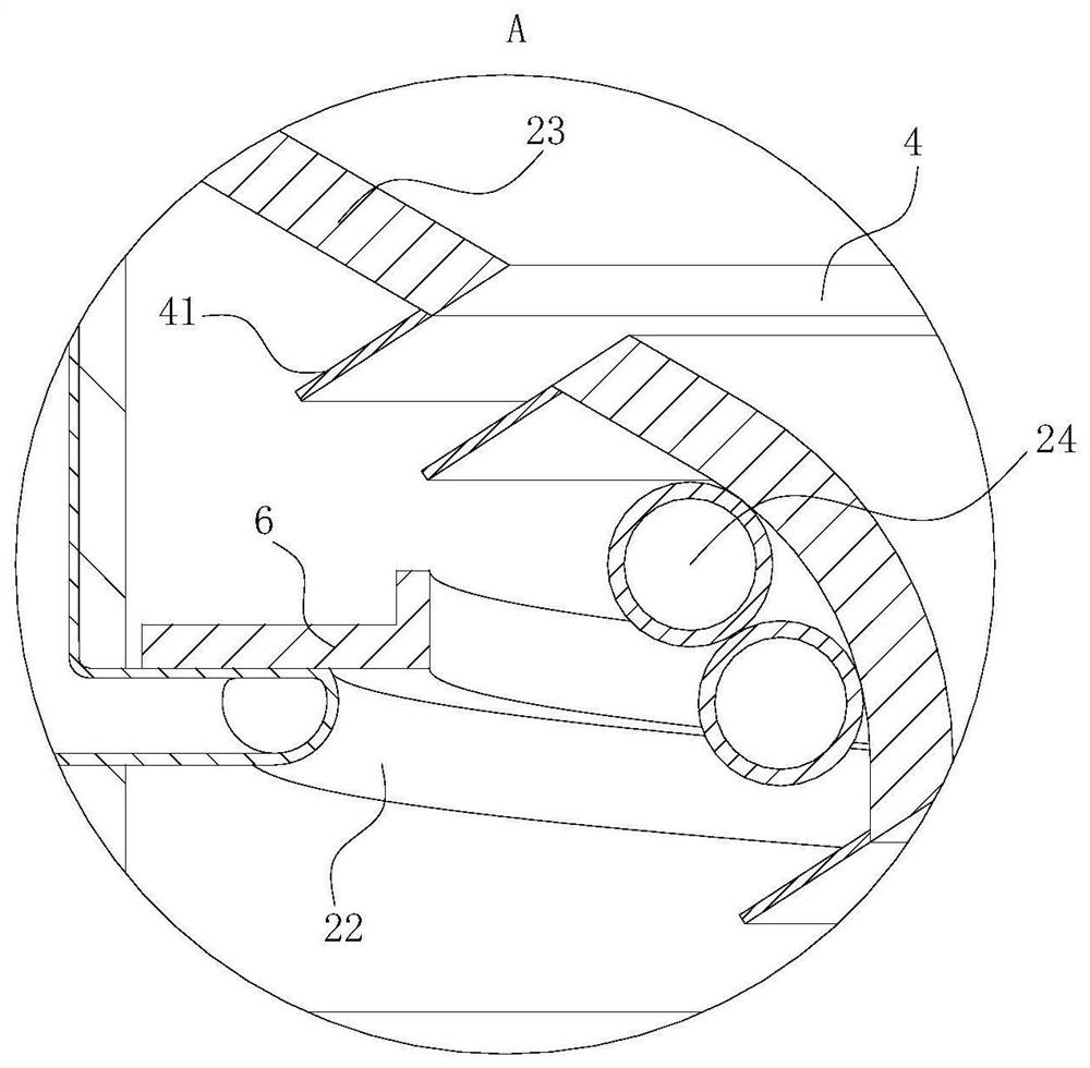
The invention belongs to the technical field of heat recovery, and particularly relates to a condensation heat recovery system for a power plant. The condensation heat recovery system comprises a condensation tank, a water inlet pipe, a water outlet pipe and a heat exchanger; the condensation tank is of a cylindrical cavity type structure; the middle part of the side wall of the condensation tank is fixedly connected with a steam pipe; the side, away from the condensation tank, of the steam pipe is externally connected with a turbine; the steam pipe extends into the condensation tank, and an opening of the steam pipe faces downwards in the condensation tank; the bottom of the condensation tank is fixedly connected with a condensate water pipe; and the condensate water pipe is externally connected with a condensate water pump and is used for pumping condensate water. According to the condensation heat recovery system provided by the invention, by arranging the condensation tank and the heat exchanger, heat is continuously pumped through circulation of circulating water and then gathered as a high-temperature heat source to be conveniently utilized; meanwhile, under the action of two spiral pipes, a heat exchange sheet neutralizes the temperature of the two spiral pipes and then exchanges heat with steam, so that the temperature of the part, located in the condensation tank, of the circulating water is balanced; and increase of a supercooling degree of the condensate water caused by a local low temperature is avoided.

Description

technical field [0001] The invention belongs to the technical field of heat recovery, in particular to a condensation heat recovery system of a power plant. Background technique [0002] In the prior art, most of the circulating water in the condensate system of the power plant absorbs heat during operation and is directly discharged to the outside through the cooling tower and the cold air island, resulting in a large amount of heat loss. Low temperature, maintained at 30-50°C all the year round, making it difficult to recover heat. The research and development of heat pump technology in the existing technology facilitates the recovery of condensation heat in circulating water. During the circulation process, the circulating water temperature at the water inlet is low during the process of condensing steam, which will easily lead to a decrease in the pressure of the condensation zone and an increase in the vacuum degree, which in turn leads to an increase in the supercoolin...

Claims


Application Information

Patent Timeline
Patent Type & Authority Applications(China)
IPC IPC(8): F28B1/02F28B9/06F28B9/08F28F1/12F22B37/54F28B9/10F25B30/02
CPCF28B1/02F28B9/06F28B9/08F28F1/12F22B37/54F28B9/10F25B30/02
Inventor 邵海江张义生张付宝
Owner 巢湖市鑫皖新能源有限公司
Learn More