Vacuumizing system suitable for mass spectrometer

A vacuum pumping system and mass spectrometer technology, applied in the field of mass spectrometers, can solve the problems of long sample waiting time, large volume, and bulky mass spectrometer, and achieve the advantages of shortening the waiting time for sample injection, reducing the gas path structure, and improving the detection efficiency. Effect

Pending Publication Date: 2021-05-14
AUTOBIO LABTEC INSTR CO LTD
View PDF0 Cites 0 Cited by
  • Summary
  • Abstract
  • Description
  • Claims
  • Application Information

AI Technical Summary

Problems solved by technology

However, due to the relatively long pre-pumping time of the mechanical pump, the waiting time for samples is relatively long, which cannot meet the rapid detection requirements of high-throughput samples.
[0005] For this reason, existing high-power mechanical pumps are usually use

Method used


Image

  • Vacuumizing system suitable for mass spectrometer
  • Vacuumizing system suitable for mass spectrometer
  • Vacuumizing system suitable for mass spectrometer

Examples


Embodiment approach 1

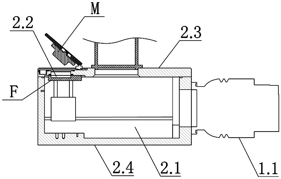
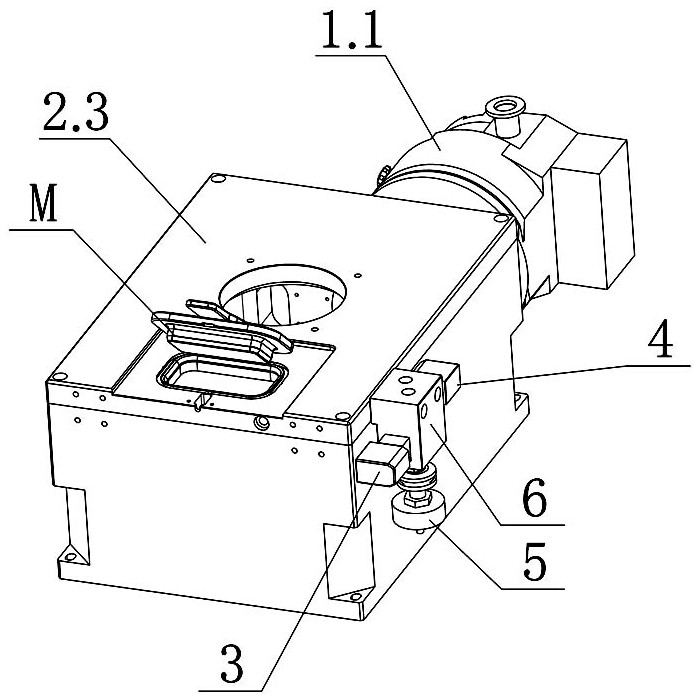
[0039] Such as Figure 1-3 As shown, the vacuum pumping system suitable for a mass spectrometer described in this embodiment includes a first pumping unit and a second pumping unit, and the first pumping unit includes a molecular pump 1.1 and a mechanical pump 1.2 (working pressure at 10 -2 Pa), the pumping port of the molecular pump 1.1 is connected with the vacuum chamber 2.1 of the mass spectrometer; before the detection (that is, the sample is detected by the mass spectrometer), use the mechanical pump 1.2 to pre-pump the molecular pump 1.1, and then start the molecular pump 1.1 , using the molecular pump 1.1 to draw negative pressure on the vacuum chamber 2.1 (the mechanical pump 1.2 continues to work), so that the negative pressure of the vacuum chamber 2.1 maintains the high vacuum degree required by the sample (about 10 -6 mbar);

[0040]The second pumping unit includes a vacuum air circuit, an inlet valve 3 and a pre-extraction valve 4, one end of the vacuum air ci...

Embodiment approach 2

[0056] The difference between the vacuum pumping system described in this embodiment and the first embodiment is that the vacuum pumping system further includes a negative pressure buffer unit. Specifically: as Figure 11 As shown, the negative pressure buffer unit includes a buffer chamber 7.1 and a buffer valve 7.2. The first interface of the buffer chamber 7.1 communicates with the suction port of the mechanical pump 1.2 through the first pipeline, and the second interface of the buffer chamber 7.1 communicates with the air inlet of the mechanical pump 1.2 through the second pipeline. The transition chamber 2.2 is connected, and the other end of the second pipeline is sealed and inserted into the connection port on the sealing cover M plate corresponding to the transition chamber 2.2. The buffer valve 7.2 (preferably a two-position two-way electric valve) is connected to the on the pipeline.

[0057] In actual installation, the buffer valve 7.2 can also be integrally insta...

Embodiment approach 3

[0062] The difference between the vacuum system described in this embodiment and the second embodiment is that the negative pressure buffer unit is different. Specifically: as Figure 12 As shown, the negative pressure buffer unit includes a buffer chamber 7.1 and a buffer valve 7.2 (the buffer valve 7.2 is preferably a two-position two-way solenoid valve). The first interface of the buffer chamber 7.1 communicates with the vacuum chamber 2.1 through the pre-pumping valve 4. The second interface of 7.1 communicates with the transition chamber 2.2 through the buffer valve 7.2;

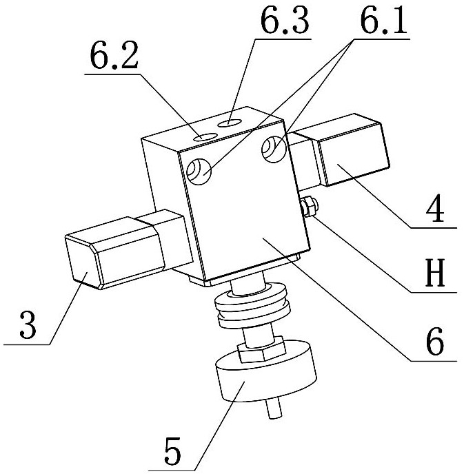
[0063] One interface of the pre-pumping valve 4 communicates with the fourth passage 6.9, making it communicate with the vacuum chamber 2.1 through the fourth passage 6.9, the second connecting hole 6.3, and the second connecting passage 6.5; the other port of the pre-pumping valve 4 It communicates with the buffer cavity 7.1 through the connecting tube, and the other interface of the buffer cavity 7.1...


PUM


Abstract

The invention discloses a vacuumizing system suitable for a mass spectrometer. The vacuumizing system comprises a first air exhaust unit and a second air exhaust unit. The first air exhaust unit comprises a molecular pump and a mechanical pump which are connected with each other, and an air exhaust opening of the molecular pump is connected with a vacuum chamber of the mass spectrometer; and the second air exhaust unit comprises a vacuum air path, an air inlet valve and a pre-extraction valve, one end of the vacuum air path is connected with a transition chamber of the mass spectrometer, the other end of the vacuum air path is divided into two paths, the first path is connected with the outside atmosphere through the air inlet valve, and the second path is connected with the vacuum chamber through the pre-extraction valve. According to the invention, the connection between the vacuum chamber and the transition chamber is realized by utilizing the pre-extraction valve, and the molecular pump can indirectly vacuumize the transition chamber through the vacuum chamber during vacuumizing so that the rapid pre-pumping of the transition chamber is realized, sample injection waiting time of a sample is greatly shortened, and the detection efficiency is improved.

Description

technical field [0001] The invention relates to a mass spectrometer, in particular to a vacuum pumping system suitable for the mass spectrometer. Background technique [0002] Matrix-assisted laser desorption ionization time-of-flight mass spectrometer (MALDI-TOF-MS, hereinafter referred to as mass spectrometer) needs to perform sample analysis in a vacuum state, that is, the sample is placed in the vacuum chamber of the mass spectrometer and the sample is dissociated. Such as figure 1 As shown, most of the existing molecular pumps are used to draw vacuum to the vacuum chamber 2.1 (enclosed by the box body 2.4 and the cover plate 2.3) to ensure the vacuum degree of the vacuum chamber; at the same time, in order to protect the molecular pump 1.1, a Equipped with a backing mechanical pump. [0003] The vacuum chamber 2.1 of the mass spectrometer is relatively large, and the vacuuming time of the vacuum chamber is long. If the sample is taken and placed by repeatedly replenis...

Claims


Application Information

Patent Timeline
IPC IPC(8): H01J49/24
CPCH01J49/24
Inventor 李向广尚元贺韩乐乐曹洁茹蔡克亚
Owner AUTOBIO LABTEC INSTR CO LTD
Why Eureka
Try Eureka