Wireless charging magnetic positioning structure, wireless charging module and wireless charger
A wireless charging and magnetic positioning technology, which is applied in current collectors, battery circuit devices, electric vehicles, etc., can solve single problems, achieve the effects of increasing magnetic field strength, achieving precise positioning, and improving charging efficiency
- Summary
- Abstract
- Description
- Claims
- Application Information
AI Technical Summary
Problems solved by technology
Method used
Image
Examples
Embodiment 1
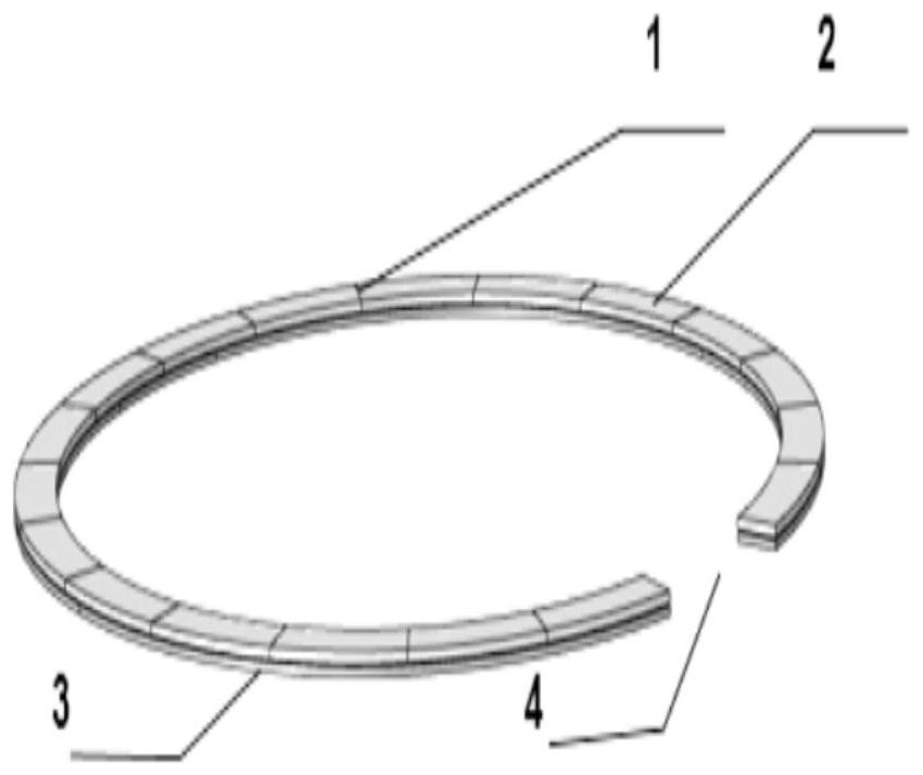
[0073] Such as figure 1 As shown, a wireless charging magnetic positioning structure includes a first magnet 1 and a magnetically conductive sheet 3;
[0074] The magnetically conductive sheet 3 is attached to one side of the first magnet 1;
[0075] Preferably, the first magnet 1 has a through hole 4 for leading out the coil leads, thereby reducing the thickness of the wireless charging module;
[0076] Wherein the shape of the first magnet 1 can be set according to actual needs, such as the first magnet 1 can be a ring structure, such as a square ring, a rectangular ring or a ring, etc.;
[0077] In an optional embodiment, the first magnet 1 includes more than two second magnets 2, and the two or more second magnets 2 are spliced into different rings around the wireless charging coil, such as square rings, rectangular Ring or ring, etc.;
[0078] The magnetization directions of the second magnets 2 are the same;
[0079] Wherein the second magnet 2 can adopt magnetic m...
Embodiment 2
[0083] On the basis of Embodiment 1, the magnetic conductive sheet 3 is further defined:
[0084] The material of the magnetic conductive sheet 3 includes silicon steel sheet, low carbon steel, stainless steel, ferrite or metal powder core material;
[0085] The shape of the magnetic conductive sheet 3 is adapted to the shape of the first magnet 1;
[0086] This setting can not only reduce the magnetic flux leakage of the first magnet, but also avoid excessive impact on the volume of the wireless charging module;
[0087] In another optional embodiment, the shape of the magnetically conductive sheet 3 can be set according to actual needs, such as a ring shape such as Figure 4 and Figure 5 As shown, it can also be a square or a rhombus, etc.;
[0088] Wherein the area of the magnetic conductive sheet 3 can be set larger, for example, larger than the area of the first magnet 1, the greater the magnetic field strength of the magnetic positioning structure, the higher the...
Embodiment 3
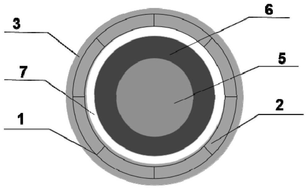
[0093] Such as figure 2 and image 3 As shown, a wireless charging module includes the wireless charging magnetic positioning structure described in Embodiment 1 or Embodiment 2;
[0094] It also includes a wireless charging coil 5 and a magnetic isolation sheet 6;
[0095] The wireless charging coil 5 is bonded to one side of the magnetic isolation sheet 6 through an adhesive layer 8;
[0096] Wherein, the wireless charging coil 5 is a coil made of copper material, and its size is determined by product design requirements;
[0097] In an optional embodiment, the wireless charging coil 5 is used to release electric energy and convert it into magnetic energy, and the material of the corresponding magnetic isolation sheet 6 includes soft magnetic ferrite, amorphous, nanocrystalline, Permalloy or silicon steel soft magnetic material;
[0098] In another optional embodiment, the wireless charging coil 5 is used to receive magnetic energy and convert it into electrical energy,...
PUM
 Abstract
Description
Claims
Application Information
 - R&D
- Intellectual Property
- Life Sciences
- Materials
- Tech Scout
- Unparalleled Data Quality
- Higher Quality Content
- 60% Fewer Hallucinations
Browse by: Latest US Patents, China's latest patents, Technical Efficacy Thesaurus, Application Domain, Technology Topic, Popular Technical Reports.
© 2025 PatSnap. All rights reserved.Legal|Privacy policy|Modern Slavery Act Transparency Statement|Sitemap|About US| Contact US: help@patsnap.com


