Manufacturing device for denitration agent applied to industrial waste gas/flue gas

A technology for manufacturing equipment and industrial waste gas, applied in gas treatment, membrane technology, dispersed particle separation, etc., can solve the problems of poor denitrification quality and high cost of denitrification

Inactive Publication Date: 2021-05-18
东莞市顶盛环保科技有限公司
View PDF1 Cites 0 Cited by
  • Summary
  • Abstract
  • Description
  • Claims
  • Application Information

AI Technical Summary

Problems solved by technology

[0005] In order to overcome the disadvantages of high cost and poor denitrification quality of waste gas, the technical problem is to provide a deni

Method used


Image

  • Manufacturing device for denitration agent applied to industrial waste gas/flue gas
  • Manufacturing device for denitration agent applied to industrial waste gas/flue gas
  • Manufacturing device for denitration agent applied to industrial waste gas/flue gas

Examples


Embodiment 1

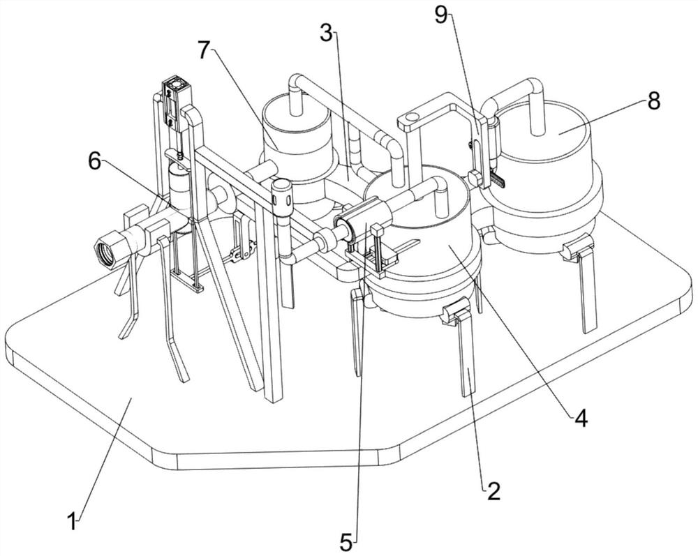
[0067] A denitration agent manufacturing device for industrial waste gas / flue gas, such as figure 1 As shown, it includes a bottom plate 1, a first frame 2, a connecting plate 3, a gas washing mechanism 4 and a gas drying mechanism 5. There are three sets of first frames 2 on the upper right of the bottom plate 1, and each group has three first frames 2. The connecting plate 3 is provided in the upper middle of the bottom plate 1, and the top of a group of first racks 2 on the left front side is provided with a gas washing mechanism 4, which is connected with the connecting plate 3, and a gas drying mechanism is installed on the left side of the bottom plate 1 5. The gas drying mechanism 5 is connected to the gas scrubbing mechanism 4 .

[0068]When the factory reduces the nitrate content in the exhausted flue gas, the required cost is relatively high. The present invention helps people reduce the cost of processing the flue gas. First, ammonia water is added in the gas scrubb...

Embodiment 2

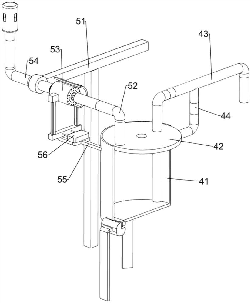
[0070] On the basis of Example 1, such as figure 2 As shown, the scrubbing mechanism 4 includes a washing tub wall 41, a first top cover 42, a first air pipe 43 and a backflow pipe 44, and the top of a group of first racks 2 on the left front side is provided with a washing tub wall 41, and the washing tub wall 41 is connected with the connecting plate 3, the top of the washing bucket wall 41 is provided with a first top cover 42, the rear of the first top cover 42 is provided with a first air pipe 43, and the back side of the washing bucket wall 41 is provided with a backflow pipe 44, and the backflow pipe 44 It is connected with the first air pipe 43 .

[0071] First, add ammonia water in the washing bucket wall 41, so that the liquid level of the ammonia water is not over the first air pipe 43, the first top cover 42 prevents the ammonia water from evaporating, and the smoke is discharged into the washing bucket wall 41 through the first air pipe 43, so that the smoke The...

Embodiment 3

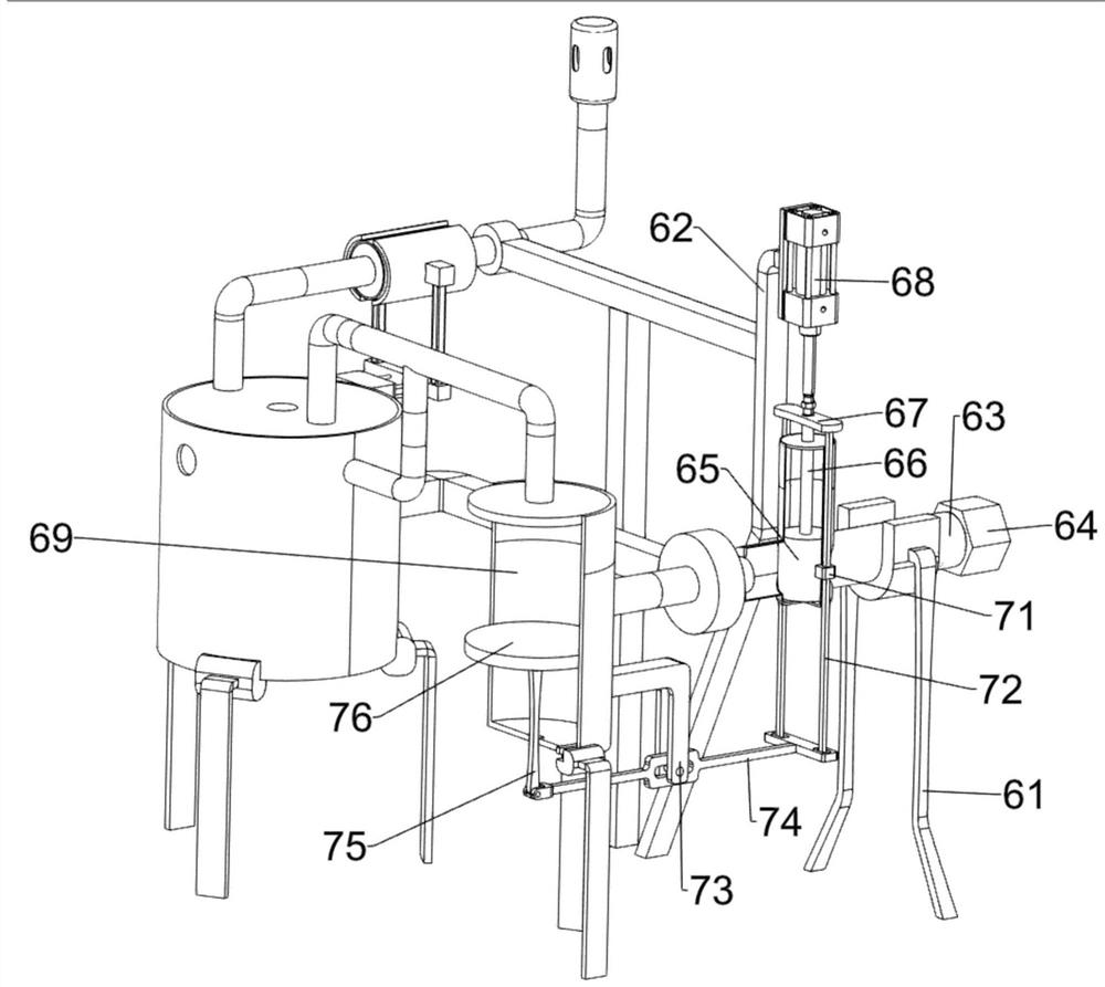
[0075] On the basis of Example 2, such as figure 1 , image 3 and Figure 4 As shown, an air intake mechanism 6 is also included. An air intake mechanism 6 is provided on the upper left rear side of the bottom plate 1. The air intake mechanism 6 is connected with the first frame 2 and the connecting plate 3. The air intake mechanism 6 includes an air injection barrel. 69. The second frame 61, the third frame 62, the air duct 63, the butt nut 64, the first piston 65, the first pull rod 66, the connection block 67 and the cylinder 68, a group of the first frame 2 on the left rear side An air injection barrel 69 is provided on the top, and the air injection barrel 69 is connected with the first air pipe 43 and the connecting plate 3. The second rack 61 is provided on the left rear part of the bottom plate 1, and two second racks are provided on the left rear part of the bottom plate 1. Three frames 62, the third frame 62 on the front side is connected with the first connecting ...


PUM


Abstract

The invention relates to a flue gas denitration device, in particular to a manufacturing device for denitration agent applied to industrial waste gas/flue gas. The invention provides the manufacturing device for denitration agent applied to industrial waste gas/flue gas and having the advantages of low waste gas denitration cost and good denitration quality. The manufacturing device comprises: a bottom plate and first racks, wherein three groups of the first racks are arranged on the bottom plate, and each group of the first racks comprises three first racks; a connecting plate, which is arranged on the bottom plate; a gas washing mechanism, which is arranged on one group of the first racks and is connected with the connecting plate; and a gas drying mechanism, which is arranged on the bottom plate and is connected with the gas washing mechanism. According to the invention, the effect of reducing the flue gas denitration cost is achieved; and through cooperation of the gas washing mechanism and the gas drying mechanism, nitrate in flue gas can be removed according to the principle that nitrate reacts with ammonia to generate ammonium nitrate, and therefore, the denitration cost is reduced.

Description

technical field [0001] The invention relates to a flue gas denitration device, in particular to a denitration agent manufacturing device for industrial waste gas / flue gas. Background technique [0002] Factory waste gas or flue gas contains a large amount of nitrate, and the waste gas containing nitrate is directly discharged into the atmosphere, which will cause serious pollution to the environment. At present, when factories process the nitrate in flue gas, the cost is relatively high, causing some small factories to directly discharge The exhaust gas may only be treated simply, and the exhaust gas with simple treatment can only remove part of the nitrate. [0003] The publication number is CN210434293U, which discloses a waste gas denitrification device, including a denitrification chamber and a movable mechanism. An air inlet is provided on the left side of the outer wall of the denitrification chamber, and a power mechanism is arranged in the middle of the right side of...

Claims


Application Information

Patent Timeline
IPC IPC(8): B01D53/56B01D53/79B01D53/26B01D53/04
CPCB01D53/0438B01D53/261B01D53/56B01D53/79B01D2251/2062B01D2253/102B01D2258/0283
Inventor 周文圣周文忠
Owner 东莞市顶盛环保科技有限公司
Why Eureka
Try Eureka