Process for realizing low-cost denitration by utilizing waste heat of sintered ores to heat sintering waste gas

A low-cost technology for sintering ore, which is applied in the field of waste heat utilization and sintering sintering, and can solve the problem of high operation cost of sintering and denitration

Active Publication Date: 2018-12-04
ZHONGYE-CHANGTIAN INT ENG CO LTD
View PDF6 Cites 5 Cited by
  • Summary
  • Abstract
  • Description
  • Claims
  • Application Information

AI Technical Summary

Problems solved by technology

[0005] In order to reduce the total amount of sintering flue gas terminal treatment, improve the utilization rate of residual energy in the sintering system, and solve the long-standing problem of high operating cost of SCR technology applied to sintering denitrification, the present invention provides a process for denitrification by using sinter waste heat to heat sintering waste gas , the NO in the flue gas of the sintering machine x The flue gas with high concentration is input into the cooling system as the cooling medium to cool the sintering ore. After passing through the cooling system, the flue gas of this part of the sintering machine can be heated up to 260-480 °C, and then this part of the flue gas is input into the denitrification system for denitrification treatment, and then Carry out waste heat utilization, dust removal, and desulfurization treatment to meet the emission requirements; at the same time, NO in the flue gas of the sintering machine x Flue gas with a low concentration can directly meet the emission requirements after being desulfurized by waste heat utilization and dust removal, thereby reducing the processing capacity of the denitrification system

Method used


Image

  • Process for realizing low-cost denitration by utilizing waste heat of sintered ores to heat sintering waste gas
  • Process for realizing low-cost denitration by utilizing waste heat of sintered ores to heat sintering waste gas
  • Process for realizing low-cost denitration by utilizing waste heat of sintered ores to heat sintering waste gas

Examples


Embodiment 1

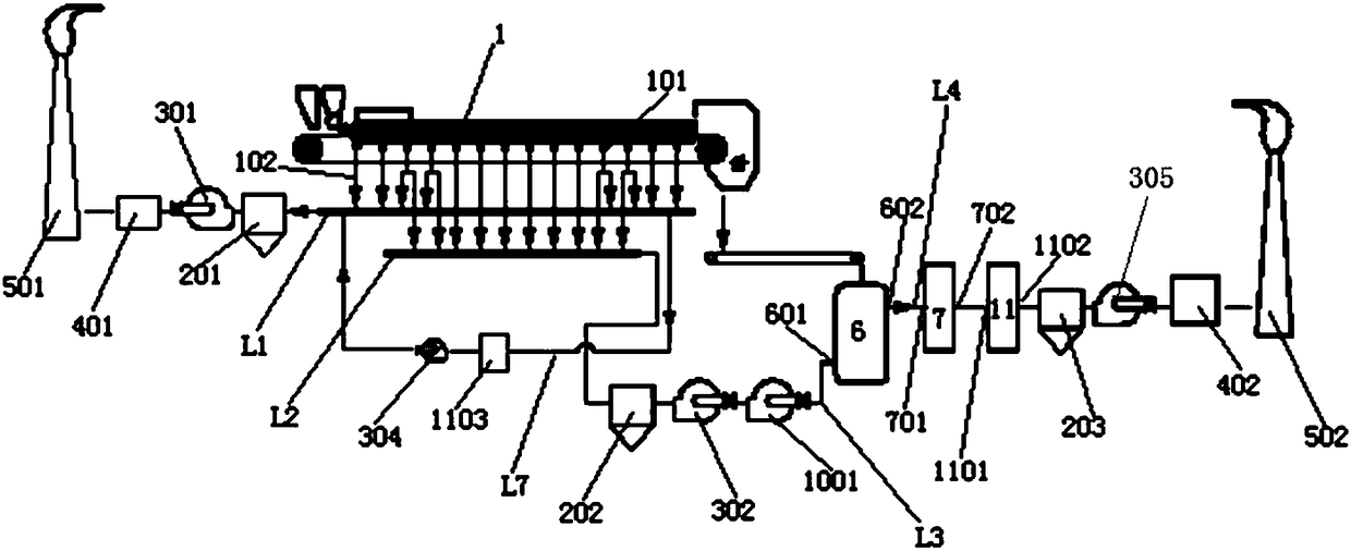
[0143] A system that uses sinter waste heat to heat sinter waste gas to achieve low-cost denitrification, the system includes:

[0144] A sintering machine 1, 28 bellows 101 are arranged under the trolley of the sintering machine 1;

[0145] The non-denitration flue gas pipeline L1 and the denitrification flue gas pipeline L2 provided under the sintering machine 1,

[0146] cooling system 6, and

[0147] Denitrification system 7;

[0148] Among them, according to the running direction of the mineral material on the sintering machine 1, the bellows of the sintering machine 1 are divided into 5 sections, the first section includes 3 bellows, the second section includes 2 bellows, and the third section The first section includes 16 bellows, the fourth section includes 2 bellows, and the fifth section includes 5 bellows;

[0149] Each wind box 101 belonging to the first section is connected to the non-denitration flue gas pipeline L1 through its respective wind box branch pipe ...

Embodiment 2

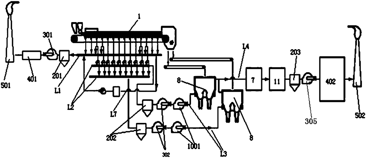
[0155] Embodiment 1 is repeated, except that a fourth dust collector 204 is provided on the second flue gas delivery pipeline L4. The second flue gas delivery pipe L4 is connected to the flue gas inlet 701 of the denitrification system 7 after passing through the third waste heat recovery device 1104 . A first temperature detector 1401 and a concentration detector 15 are installed on the non-denitration flue gas pipeline L1. A second temperature detector 1402 is installed on the denitration flue gas pipeline L2. The flue gas outlet 1102 of the first waste heat recovery device 11 is connected to the flue gas inlet of the second desulfurization system 402 through the fifth exhaust fan 305 after passing through the third dust collector 203 . The wind box branch pipes 102 connected to the wind boxes 101 belonging to the fifth section are all directly connected to the third flue gas delivery pipeline L7, and then connected to the non-denitration flue gas pipeline L1 through the fo...

Embodiment 3

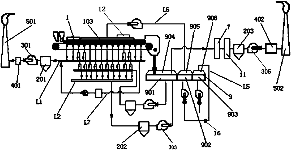
[0157] Example 2 was repeated, except that the vertical cooler 8 was replaced by an annular cooler 9 . The annular cooler 9 includes a high temperature section 901 , a medium temperature section 902 and a low temperature section 903 . The denitrification flue gas pipeline L2 passes through the second dust collector 202 and is connected to the air inlet of the high temperature section 901 of the annular cooler 9 . Above the high temperature section 901 is provided a wind cover 904 for the high temperature section of the ring cooler. The air outlet of the wind hood 904 of the high temperature section of the ring cooler is connected to the flue gas inlet 701 of the denitrification system 7 . A third exhaust fan 303 is provided on the first flue gas conveying pipe L3. A sealing cover 103 is provided above the trolley of the sintering machine. The air inlet of the low-temperature section 903 of the annular cooler 9 communicates with the atmosphere. Above the low temperature sec...


PUM


Abstract

The invention provides a process for realizing low-cost denitration by utilizing waste heat of sintered ores to heat waste gas. According to the process, flue gas with relatively high NOx concentration in flue gas of a sintering machine is used as a cooling medium to be input into a cooling system for cooling the sintered ores, the part of the flue gas of the sintering machine can be heated to 260-480 DEG C after passing through the cooling system, then the part of the flue gas is input into a denitration system for denitration treatment, then waste heat utilization, dust removal and desulfurization treatment are carried out, and then the emission requirement is met; flue gas with relatively low NOx concentration in the flue gas of the sintering machine undergoes the desulfurization treatment after undergoing the waste heat utilization and the dust removal, and the emission requirement can be met directly, so that the flue gas treatment amount of the denitration system is reduced; andtherefore, the waste heat of the sintered ores in the cooling system is effectively utilized in the process, then the sintering flue gas can reach the required temperature in the denitration system, energy conservation and emission reduction are achieved, and meanwhile, the operation cost of sintering flue gas treatment is reduced.

Description

technical field [0001] The invention relates to a sintering flue gas denitrification process, in particular to a process for realizing low-cost denitrification by using sinter waste heat to heat sinter waste gas, and belongs to the fields of sinter sintering and waste heat utilization. Background technique [0002] The iron and steel industry is the foundation and pillar industry of my country's national economy. my country's iron and steel smelting is mainly based on the long process of "sintering (pellet) coking-blast furnace-converter". More than 75% of the blast furnace charge comes from sintering ore, and the annual output has reached nearly 1 billion tons, it can be seen that sintering production plays a vital role in the preparation of raw materials before ironmaking. At the same time, the sintering process is also a high energy consumption and high pollution concentrated link in the iron and steel process. SO x , NO x , persistent organic compounds, heavy metals an...

Claims


Application Information

Patent Timeline
Patent Type & Authority Applications(China)
IPC IPC(8): F27D17/00F27D15/02F27D19/00
CPCF27D15/02F27D17/001F27D17/004F27D17/008F27D19/00F27M2003/04
Inventor 周志安王兆才谭诚李文林储太山贺新华代友训李康
Owner ZHONGYE-CHANGTIAN INT ENG CO LTD
Why Eureka
Try Eureka