High-speed air suspension compressor for fuel cell, fuel cell system and vehicle

An air suspension and fuel cell technology, applied in fuel cells, liquid fuel engines, electrical components, etc., can solve problems such as poor cooling effect, low speed, and large compressor volume

Inactive Publication Date: 2021-05-18
HAINAN JIRUI HAOHAN POWER SYST TECH CO LTD
View PDF14 Cites 3 Cited by
  • Summary
  • Abstract
  • Description
  • Claims
  • Application Information

AI Technical Summary

Problems solved by technology

[0010] In view of the above facts, the purpose of the present invention is to address the problems of existing compressors with large volume, low speed and poor cooling effect, and then design a high-speed air suspension compressor for fuel cells, fuel cell systems and vehicles, compressors Output compressed air to the stack for hydrogen-oxygen reaction to generate electricity

Method used


Image

  • High-speed air suspension compressor for fuel cell, fuel cell system and vehicle
  • High-speed air suspension compressor for fuel cell, fuel cell system and vehicle
  • High-speed air suspension compressor for fuel cell, fuel cell system and vehicle

Examples


Embodiment 1

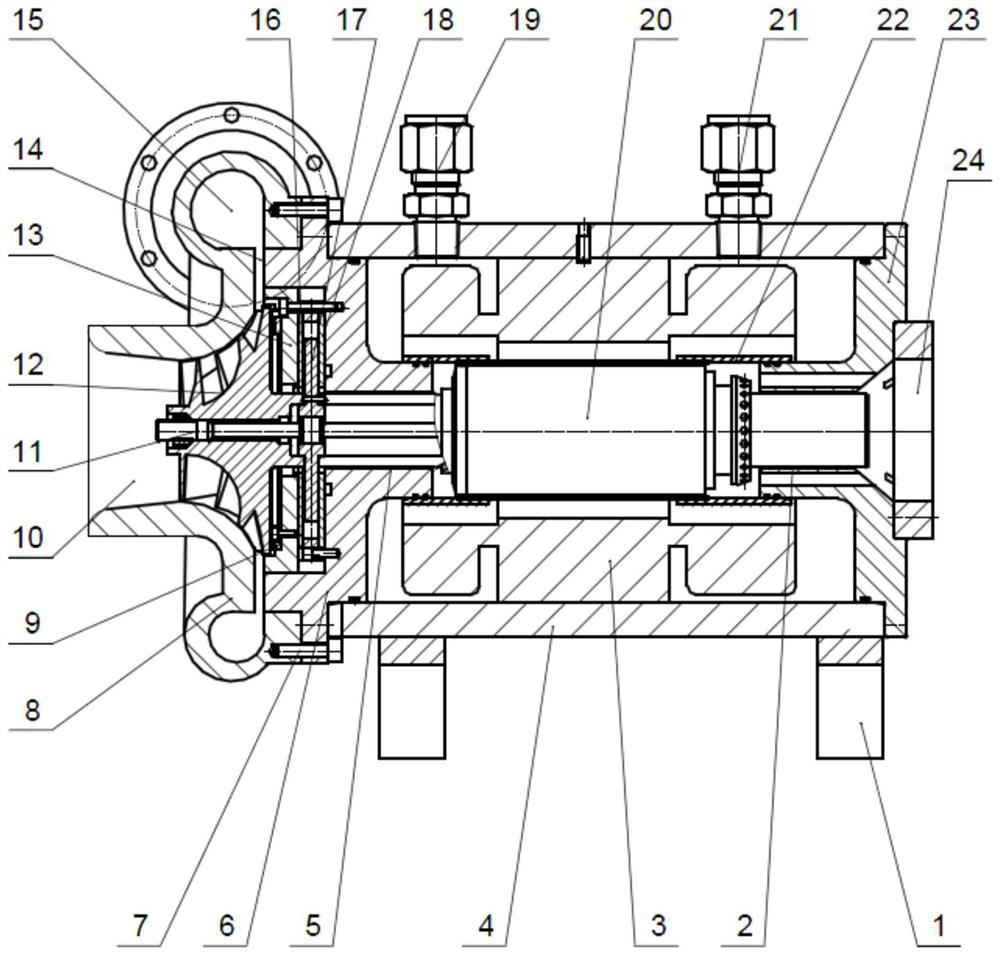
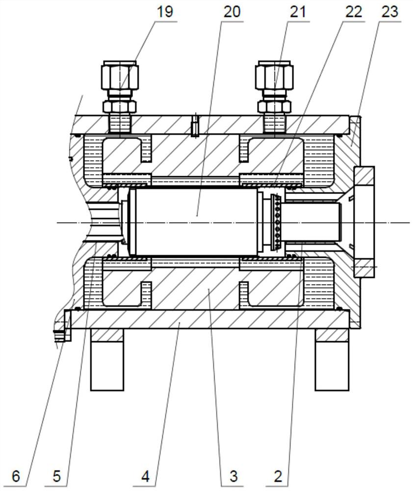
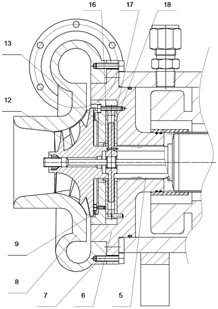
[0068] Embodiment 1: see figure 1 , 2 , 3, 4, 6, 10, a kind of fuel cell high-speed air suspension compressor of the present embodiment comprises:

[0069] Support 1, rear radial bearing 2, stator 3, housing 4, front radial bearing 5, front bearing housing 6, volute 8, labyrinth seal 9, stretching screw 11, impeller 12, thrust bearing housing 13, expansion Compressor 14, outer thrust bearing 16, thrust disc 17, inner thrust bearing 18, main shaft 20, rear bearing seat 23, rear cover 24 and partition sleeve, the partition sleeve is a three-stage split structure, including the front sleeve 26 , middle sleeve 25 and rear sleeve 22;

[0070] The shell 4 is arranged on the support 1, and the shell 4 is provided with a liquid inlet 19 and a liquid discharge port 21, and the liquid inlet 19 and the liquid discharge port 21 are connected with pipe joints;

[0071] The front bearing seat 6 is fixedly installed on the front end of the housing 4 by bolts, and the sealing ring is reali...

Embodiment 2

[0074] Embodiment 2: The difference from Embodiment 1 lies in the sealing method between the partition sleeve and the front bearing seat 6 and the rear bearing seat 23; specifically: there are sealing grooves on the outer walls of the front sleeve 26 and the rear sleeve 22, and the sealing Sealing ring is set in the groove, between the outer wall of front sleeve 26 and the inwall of front bearing block 6, install by sealing ring, between the outer wall of rear sleeve 22 and the inwall of rear bearing block 23, install by sealing ring. For details, see Figure 5 .

Embodiment 3

[0075] Embodiment 3: The difference from Embodiment 1 or Embodiment 2 is that the partition sleeve adopts an integrated manufacturing structure, and the two ends of the partition sleeve are sealed and installed with the front bearing seat 6 and the rear bearing seat 23 . For details, see Figure 9 .


PUM

PropertyMeasurementUnit
diameteraaaaaaaaaa
densityaaaaaaaaaa

Abstract

The invention discloses a high-speed air suspension compressor for a fuel cell, a fuel cell system and a vehicle, and belongs to the technical field of hydrogen fuel cell electrically-driven air compressors. The problems that an existing compressor is large in size, low in rotating speed and poor in cooling effect are solved. A stator and a main shaft are arranged in a shell. The main shaft is inserted into an inner cavity of the stator and freely rotates. A thrust disc is arranged on the rear side of an impeller, a labyrinth seal is arranged on the rear side of the outer edge of the impeller, and air flows through the labyrinth seal to cool the main shaft. A partition sleeve is arranged between the main shaft and the stator to separate the stator and the main shaft in a sealed mode, cooling liquid flows between the shell and the partition sleeve, and the stator is immersed in the cooling liquid. The stator is completely immersed in the liquid to take away most heat of a motor, the specific heat capacity of the liquid is far greater than that of air, the required cooling flow is small, the system efficiency is improved, and the effects of reducing the internal temperature of the motor and ensuring normal operation of the motor can be achieved in an extreme external environment such as a desert high-temperature dry zone.

Description

technical field [0001] The invention relates to a compressor for a fuel cell, a fuel cell system and a vehicle, in particular to a high-speed air suspension compressor for a fuel cell, a fuel cell system and a vehicle, and belongs to the technical field of hydrogen fuel cell electric drive air compressors. Background technique [0002] In terms of new energy, vehicles powered by hydrogen fuel cells have high power performance, fast hydrogen refueling, and long cruising range, which is the most strategic breakthrough for new energy vehicles in the 21st century. The hydrogen fuel cell directly outputs electric energy through the chemical reaction between hydrogen and oxygen. The power density of the hydrogen fuel cell is directly related to the air supply pressure and air flow rate of the air supply system. The high air supply pressure and high oxygen partial pressure will accelerate the reaction speed of the fuel cell and output Increased power. [0003] Air compressors can ...

Claims


Application Information

Patent Timeline
Patent Type & Authority Applications(China)
IPC IPC(8): F04D25/08F04D29/02F04D29/051F04D29/056F04D29/08F04D29/58H01M8/04089
CPCF04D25/082F04D25/0606F04D29/023F04D29/051F04D29/056F04D29/083F04D29/5806F04D29/584H01M8/04089Y02E60/50F04D17/10F04D29/284F04D29/4233F04D29/441F04D29/124
Inventor 陈亮
Owner HAINAN JIRUI HAOHAN POWER SYST TECH CO LTD
Why Eureka
Try Eureka