Wood drying device and using method thereof

A drying device and wood technology, applied in the direction of wood drying, drying, drying machine, etc., can solve the problems of high energy consumption, affecting the quality of round logs, and easy bending of round logs

Inactive Publication Date: 2021-05-18
重庆美迪智能家居股份有限公司
View PDF10 Cites 2 Cited by
  • Summary
  • Abstract
  • Description
  • Claims
  • Application Information

AI Technical Summary

Problems solved by technology

[0005] Aiming at the deficiencies of the prior art, the present invention provides a wood drying device and its use method, which solves the problem that the conventional log drying device generally consumes a lot of energy, increases the drying cost of the wood, and the It is prone to bending after drying, which seriously affects the quality of round logs

Method used


Image

  • Wood drying device and using method thereof
  • Wood drying device and using method thereof
  • Wood drying device and using method thereof

Examples


Embodiment 1

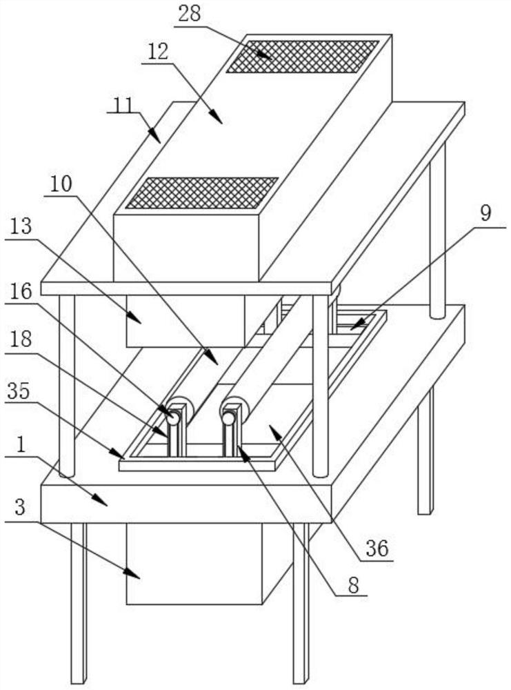
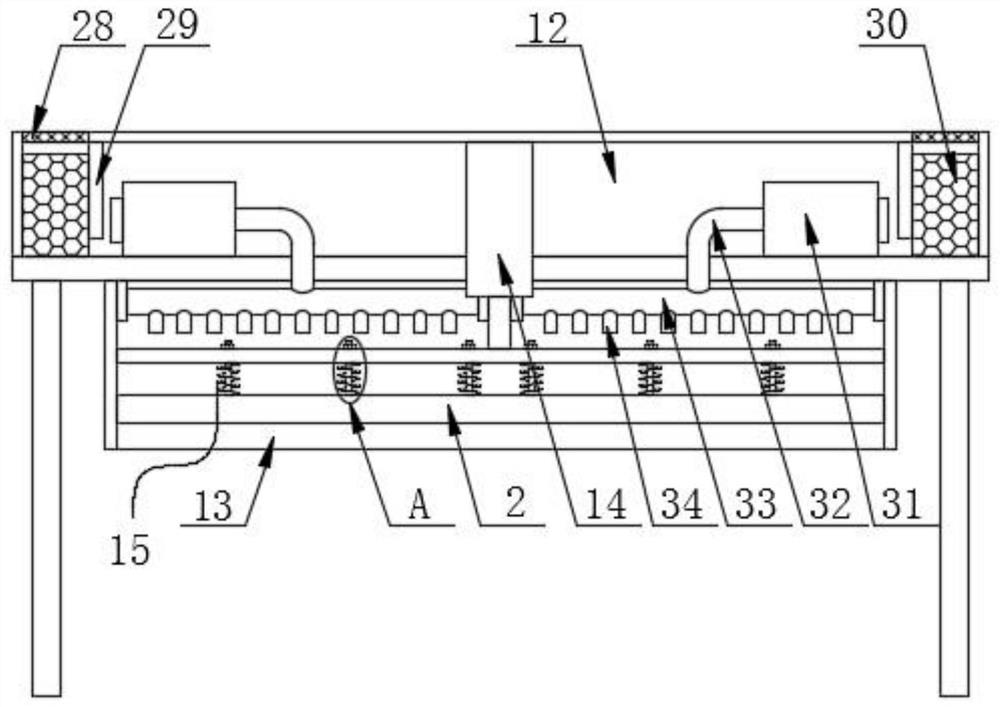
[0035] A wood drying device includes a work frame 1 and a drying board 2 arranged above the work frame 1 .

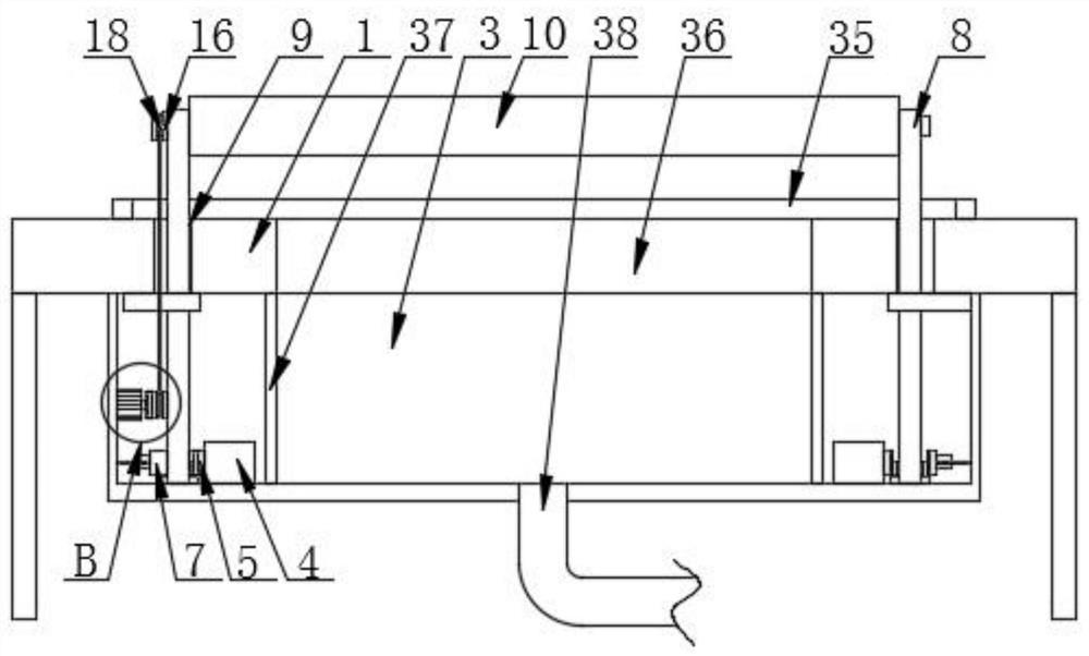
[0036]As a preferred solution, a water storage tank 3 is fixedly connected to the bottom of the top plate of the working frame 1, and a cylinder 4 is fixedly connected to the front and rear sides of the bottom of the inner cavity of the water storage tank 3. The cylinder 4 is electrically connected to the external power supply and is controlled by a control switch. The surface of the push rod of the cylinder 4 is fixedly connected with the first tooth plate 5 through the connecting plate, and the bottom of the inner cavity of the water storage tank 3 is located between the first tooth plate 5 and the opposite side of the inner wall of the water storage tank 3 through the bearing to rotate A gear 6 matched with the first tooth plate 5 is connected, the front and rear sides of the inner cavity of the water storage tank 3 are slidably installed with a second tooth plate 7 m...

Embodiment 2

[0038] This embodiment is an improvement of the previous embodiment,

[0039] A wood drying device includes a work frame 1 and a drying board 2 arranged above the work frame 1 .

[0040] As a preferred solution, a water storage tank 3 is fixedly connected to the bottom of the top plate of the working frame 1, and a cylinder 4 is fixedly connected to the front and rear sides of the bottom of the inner cavity of the water storage tank 3. The cylinder 4 is electrically connected to the external power supply and is controlled by a control switch. The surface of the push rod of the cylinder 4 is fixedly connected with the first tooth plate 5 through the connecting plate, and the bottom of the inner cavity of the water storage tank 3 is located between the first tooth plate 5 and the opposite side of the inner wall of the water storage tank 3 through the bearing to rotate A gear 6 matched with the first tooth plate 5 is connected, the front and rear sides of the inner cavity of the ...


PUM


Abstract

The invention discloses a wood drying device and a using method thereof. The wood drying device comprises a working frame and a drying plate arranged above the working frame, a water storage tank is fixedly connected to the bottom of a top plate of the working frame, and air cylinders are fixedly connected to the front side and the rear side of the bottom of an inner cavity of the water storage tank correspondingly. The invention relates to the technical field of wood processing. According to the wood drying device and the using method thereof provided by the invention, the two supporting rollers are arranged to directly support round logs, the air cylinders, first tooth plates, gears, second tooth plates and supporting plates are arranged in a matched mode, the distance between the two supporting rollers is adjusted, and therefore the round logs with different calibers can be conveniently supported; and meanwhile, in cooperation with the arrangement of a telescopic rod and the drying plate, the axial parts of the round logs can be directly dried, and after a motor is started, the supporting rollers can be driven to rotate, so that the round logs are rotatably dried, drying is more uniform, the round logs can be compacted by the drying plate in the drying process, and the situation that the round logs are bent after being dried is effectively avoided.

Description

technical field [0001] The invention relates to the technical field of wood processing, in particular to a wood drying device and a use method thereof. Background technique [0002] Wood processing technologies include basic processing technologies such as wood cutting, wood drying, wood gluing, and wood surface decoration, as well as functional processing technologies such as wood protection and wood modification. Cutting methods include sawing, planing, milling, drilling, and sanding. Due to the influence of wood structure, texture, etc., the cutting method is different from other materials. The moisture content of wood also has an impact on the cutting process. For example, the veneer manufacturing method and the production of wood chips require wet wood cutting, and most processed parts require dry wood cutting. [0003] When drying the logs, it is usually necessary to use a clamp to clamp the logs and then rotate them for drying. Such drying devices are generally set ...

Claims


Application Information

Patent Timeline
Patent Type & Authority Applications(China)
IPC IPC(8): F26B11/18F26B21/00F26B25/02F26B25/20
CPCF26B11/18F26B21/004F26B21/003F26B25/02F26B25/20F26B2210/16
Inventor 胡海
Owner 重庆美迪智能家居股份有限公司
Why Eureka
Try Eureka