Flue gas treatment device

A technology for flue gas treatment and flue gas, which is applied in gas treatment, membrane technology, and separation of dispersed particles. The effect of reducing the amount and dust content and reducing the floor space

Pending Publication Date: 2021-05-28
BEIJING SPC ENVIRONMENT PROTECTION TECH
View PDF0 Cites 0 Cited by
  • Summary
  • Abstract
  • Description
  • Claims
  • Application Information

AI Technical Summary

Problems solved by technology

[0003] At present, most flue gas treatment devices (such as wet desulfurization towers) arrange two to three layers of nozzles in the absorption tower to spray the entire absorption tower section with a high coverage rate to achieve gas-liquid mixing, thereby achieving the removal of harmful substances. The needs of the system make the structure complex, the process complex, and occupy a large area, resulting in a large amount of construction and renovation projects, high construction and operating costs, and for some occasions with less flue gas, such as coking plants, non-ferrous metals, small boilers, etc. , because of its complex structure and large footprint, it is inconvenient to use and poor in flexibility

Method used


Image

  • Flue gas treatment device
  • Flue gas treatment device
  • Flue gas treatment device

Examples


Embodiment Construction

[0023] The present invention will be further described below in conjunction with accompanying drawing.

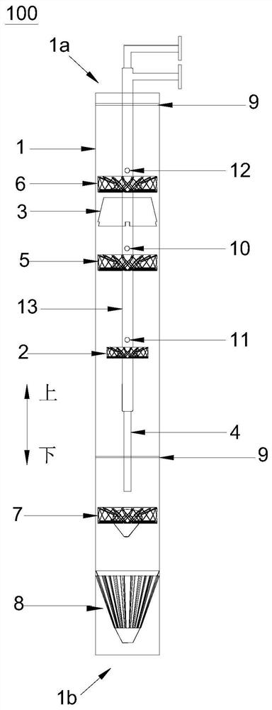
[0024] figure 1 It is a schematic structural diagram of a flue gas treatment device according to an embodiment of the present invention. Such as figure 1 As shown, the flue gas treatment device 100 is a flue gas denitrification tower, a flue gas desulfurization tower or a flue gas desulfurization and denitrification tower, and the purification liquid includes a desulfurizer (Na2CO3, NaOH or Ca(OH)2, etc.) and / or a denitrification agent. The flue gas treatment device 100 is suitable for use in flue gas discharge places of small and medium-sized boilers, steelmaking, aluminum smelting, ships, etc., and other chemical and non-electric factories.

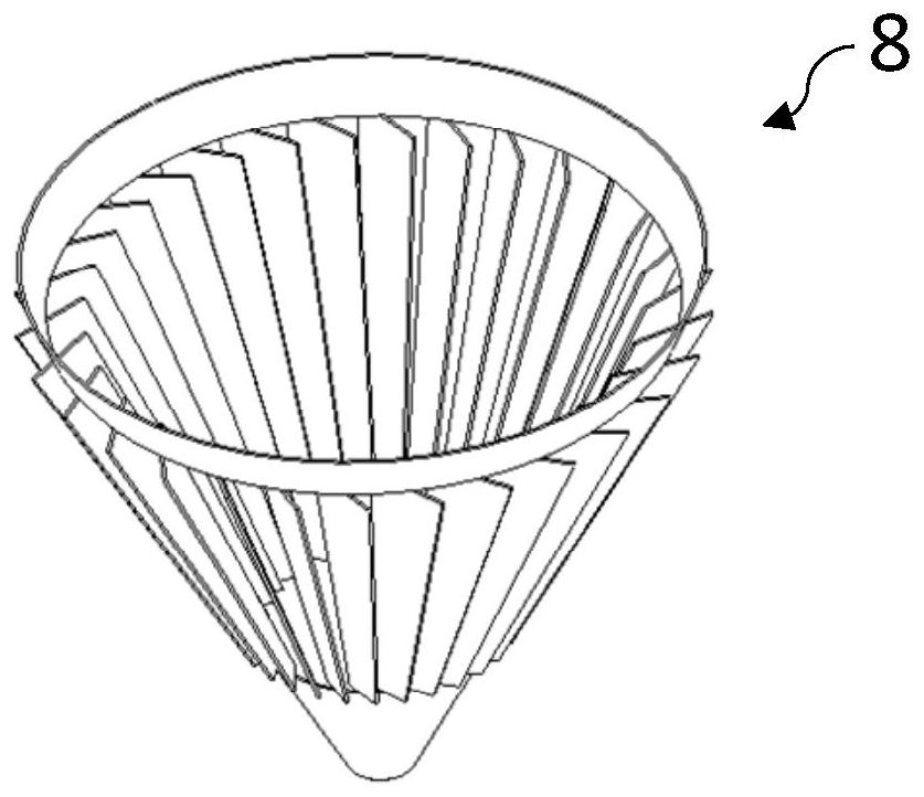
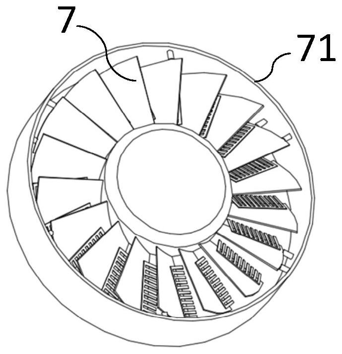
[0025] The flue gas treatment device 100 includes a cylinder body 1, a guide core pipe 4, a purification impeller 7, and a mist removal assembly (such as a first mist removal impeller 6, a second mist removal impeller 5 and / or a th...


PUM


Abstract

The invention relates to a flue gas treatment device, and the device comprises a cylinder body, which comprises a flue gas outlet arranged on the upper end part of the cylinder body and a flue gas inlet arranged on the lower end part of the cylinder body; a flow guide core tube which penetrates into the cylinder body and can release the received purification liquid into the cylinder body; a purification impeller which is arranged in the cylinder body, is positioned below the flow guide core pipe, and can guide the flue gas to rotate and promote the rotating flue gas to be mixed with the falling purification liquid; and a demisting assembly which is arranged in the cylinder body, is positioned above the purification impeller and can be used for demisting the flue gas flowing through the demisting assembly. The flue gas treatment device disclosed by the invention is simple in structure, simple in process, small in occupied area, not easy to block, relatively high in working efficiency, and capable of reducing the construction, operation and transformation cost and improving the use flexibility and the working efficiency.

Description

technical field [0001] The invention belongs to the technical field of flue gas treatment equipment, and in particular relates to a flue gas treatment device. Background technique [0002] The flue gas treatment device is to effectively remove harmful substances in the flue gas to below the specified concentration, and to avoid adverse phenomena such as corrosion or blockage of production equipment when applying equipment. At present, in the flue gas treatment devices, the reaction principle is basically the same, they all use the purification liquid (such as alkali) to react with harmful substances in the flue gas (such as sulfur, pin) and remove harmful substances, but the different realization methods of gas-liquid mixing affect the System response efficiency, resistance and reliability. [0003] At present, most flue gas treatment devices (such as wet desulfurization towers) arrange two to three layers of nozzles in the absorption tower to spray the entire absorption to...

Claims


Application Information

Patent Timeline
IPC IPC(8): B01D53/78B01D53/26
CPCB01D53/26B01D53/78B01D2251/304B01D2251/404B01D2251/604B01D2251/606B01D2257/30B01D2257/40B01D2258/0283
Inventor 宋端阳采有林田建明徐森荣周广权李计珍
Owner BEIJING SPC ENVIRONMENT PROTECTION TECH
Why Eureka
Try Eureka