
Building smashing device

A crushing device and construction technology, applied in grain processing, dispersed particle separation, chemical instruments and methods, etc., can solve the problems of unhealthy workers, affecting air quality, and reducing performance, so as to benefit human health and reduce Pollution, the effect of improving performance

Inactive Publication Date: 2021-05-28
六安十方信息科技有限公司
View PDF0 Cites 3 Cited by
  • Summary
  • Abstract
  • Description
  • Claims
  • Application Information

AI Technical Summary

Problems solved by technology

[0005] Aiming at the deficiencies of the prior art, the present invention provides a crushing device for construction, which solves the problem that the existing crushing device for construction waste will generate damp dust during use, especially when the wet construction waste is crushed. On the surface, it is easy to be clogged, which makes the crushing efficiency low, and there will be a lot of dust, which is not good for the health of the staff, and at the same time affects the air quality and reduces the problem of performance.

Method used


Image

  • Building smashing device
  • Building smashing device
  • Building smashing device

Examples


Embodiment example 1

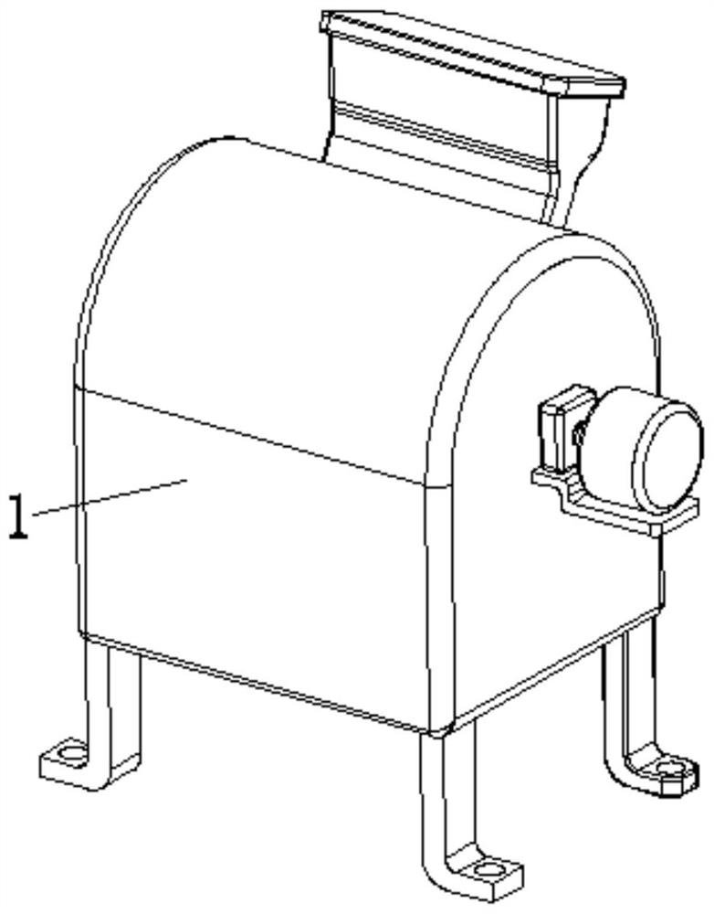
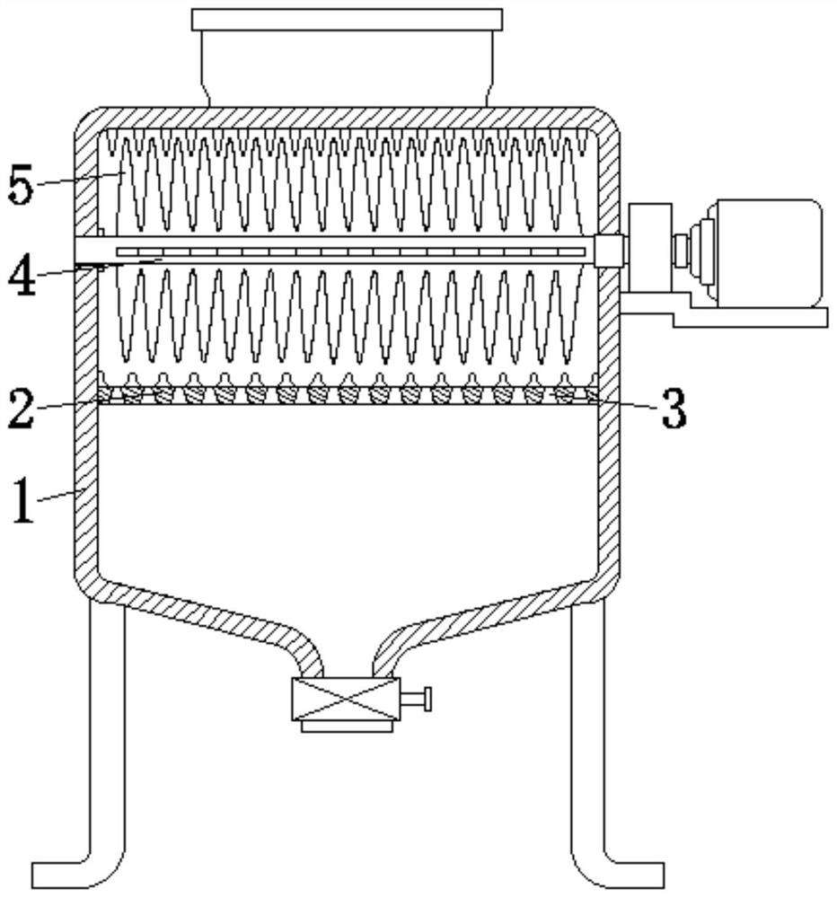
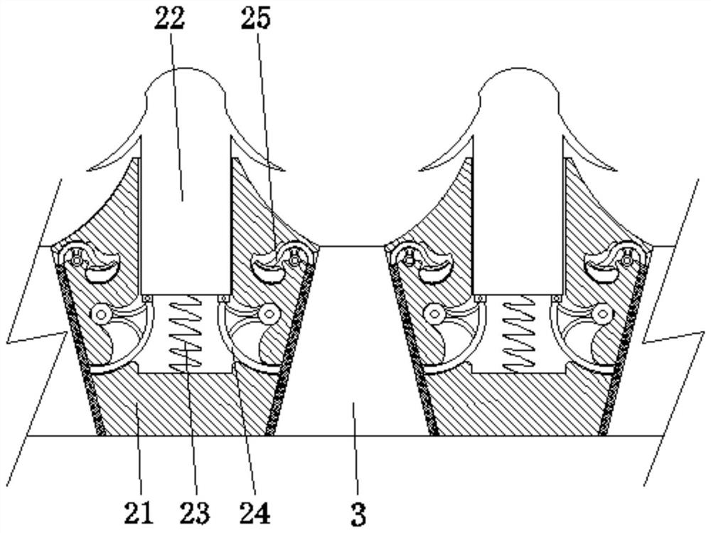
[0032] see Figure 1-7 , the present invention provides a technical solution: a crushing device for construction, comprising a crushing chamber 1, a sieve plate device 2, a sieve hole 3, a drive shaft 4, and a crushing device 5, the sieve plate device 2 is fixed on the inner wall of the crushing chamber 1 and Located in the central position, the sieve hole 3 is opened on the surface of the sieve plate device 2, the drive shaft 4 is rotatably connected between the two sides corresponding to the inner wall of the crushing chamber 1, the crushing device 5 is fixed on the surface of the drive shaft 4, and the sieve plate device 2 is set There are sieve plate body 21, pressure block 22, return spring 23, arc-shaped ejector rod 24, instigation device 25, pressure block 22 is slidably connected to the top of sieve plate body 21, return spring 23 is fixed on the bottom of pressure block 22 and sieve plate body 21, the arc-shaped ejector rod 24 is rotatably connected to the inside of t...

Embodiment example 2

[0036] The crushing device 5 is provided with a crushing main body 51, an air flow channel 52, a dust removal device 53, a channel 54, an air port 55, and a second magnetic block 56. The air flow channel 52 is set inside the crushing main body 51, and the dust removal device 53 is fixed inside the crushing main body 51. And be positioned at the position of air passage 52, passage 54 is opened in the inside of drive shaft 4, and air port 55 is provided on the surface of crushing main body 51, and passage 54 communicates with air port 55 through air passage 52, and the second magnetic block 56 is arranged on the crushing main body The inside of 51 is located at the edge, which can filter the dust generated during crushing, has the function of dust removal, reduces the spread of dust, is beneficial to human health, and reduces air pollution.

[0037] The dust removal device 53 is provided with a filter main body 531, an arc surface 532, an air outlet 533, and an air inlet 534. Th...


PUM


Abstract

The invention discloses a building smashing device. The building smashing device comprises a smashing chamber, a sieve plate device, sieve holes, a driving shaft and a smashing device body; the sieve plate device is fixed to the inner wall of the smashing chamber and located in the center; the smashing device body is fixed to the surface of the driving shaft; pressing blocks are slidably connected to the tops of sieve plate bodies; and arc-shaped ejector rods are rotationally connected into the sieve plate bodies, the top ends of the arc-shaped ejector rods are hinged to the bottom ends of the pressing blocks, and flapping devices are arranged in the sieve plate bodies and located at the positions of the sieve holes. According to the building smashing device, the purposes of preventing blockage and removing dust are achieved, wet dust adhesion is reduced, the blockage condition is avoided, the smashing efficiency is high, meanwhile, dust can be collected, dust diffusion is reduced, the dust suction amount of workers is reduced, human health is facilitated, air pollution is reduced, and the use performance is improved.

Description

technical field [0001] The invention relates to the technical field of crushing equipment, in particular to a crushing device for construction. Background technique [0002] In recent years, with the development of the economy and the acceleration of urbanization, in order to solve the problems of urban population growth and increasing shortage of land resources, urban buildings have been continuously developed to high-rise buildings. But then there is more and more construction waste. Construction waste has a wide range of erosive effects on our living environment. If construction waste is ignored for a long time, it will have a bad impact on urban environmental sanitation, living conditions, and land quality assessment. First of all, after a large amount of land is piled with construction waste, it will reduce the quality of the soil and reduce the production capacity of the soil; the construction waste is piled in the air, which affects the air quality, and some dust par...

Claims


Application Information

Patent Timeline
Patent Type & Authority Applications(China)
IPC IPC(8): B02C13/13B02C13/26B02C23/16B02C23/18B01D45/06
CPCB01D45/06B02C13/13B02C13/26B02C23/16B02C23/18B02C2023/165B02C2201/06
Inventor 冷明宇
Owner 六安十方信息科技有限公司
Learn More