A shock-absorbing damper for high-piled wharf

A shock-absorbing damping and high-pile wharf technology, applied in the field of shock-absorbing dampers, can solve the problems that shock-absorbing and isolation technologies have not been widely used, and achieve the effects of reducing movement speed, reducing damage, and increasing flow resistance

Active Publication Date: 2022-07-15
HARBIN INST OF TECH
View PDF12 Cites 0 Cited by
  • Summary
  • Abstract
  • Description
  • Claims
  • Application Information

AI Technical Summary

Problems solved by technology

[0004] However, these seismic isolation technologies have not been widely used in high-piled wharves
The mainstream high-piled wharf codes at home and abroad do not involve specific requirements for seismic isolation measures

Method used


Image

  • A shock-absorbing damper for high-piled wharf
  • A shock-absorbing damper for high-piled wharf
  • A shock-absorbing damper for high-piled wharf

Examples


specific Embodiment approach 1

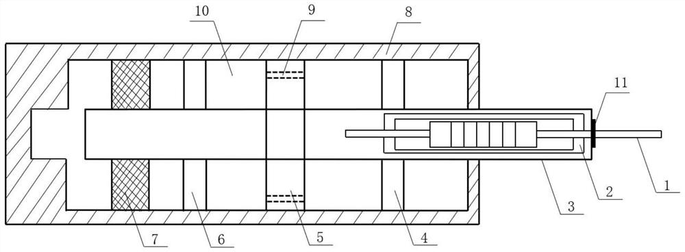
[0019] Specific implementation one: as Figure 1 to Figure 4 As shown, the present invention discloses a shock-absorbing damper for a high-piled wharf, including a magnetorheological damper 2, a frequency trigger switch 11 and a viscous damper 24; the magnetorheological damper 2 is arranged in the viscous damping In the main piston rod 3 of the damper 24 , and a frequency trigger switch 11 is arranged between the outer end of the main piston rod 3 and the magnetorheological damper 2 . When the present invention is subjected to a huge seismic load, the action of high-frequency seismic waves can excite the frequency trigger switch 11, so that the magnetorheological damper 2 is out of work, and the viscous damper 24 starts to work, thereby consuming seismic energy and achieving the purpose of shock absorption .

specific Embodiment approach 2

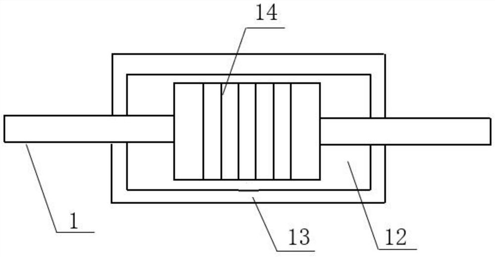
[0020] Embodiment 2: This embodiment is a further description of Embodiment 1. The magnetorheological damper 2 includes a secondary piston rod 1, a magnetorheological liquid 12, a secondary cylinder 13 and an excitation coil 14; the The outer wall of the auxiliary piston rod 1 is preferably wound with an excitation coil 14 in the middle, the auxiliary piston rod 1 and the outer ring of the excitation coil 14 are sleeved with an auxiliary cylinder 13, the auxiliary cylinder 13 is filled with magnetorheological liquid 12, and the auxiliary piston rod is One end of 1 protrudes to the outside of the main piston rod 3 , the outer wall of the auxiliary cylinder 13 is fixedly connected with the inner wall of the main piston rod 3 , and a frequency trigger switch 11 is arranged between the main piston rod 3 and the auxiliary piston rod 1 . When the present invention is subjected to the static load of the mooring ship, the excitation coil 14 inside the magnetorheological damper 2 will g...

specific Embodiment approach 3

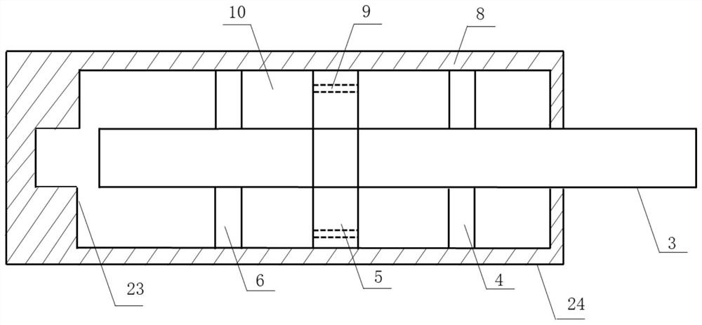
[0021] Embodiment 3: This embodiment is a further description of Embodiment 1 or 2. The viscous damper 24 includes a main piston rod 3, a right end cover 4, a piston 5, a left end cover 6, a master cylinder 8 and Damping medium 10; the main piston rod 3 is arranged horizontally and the outer side is vertically sleeved with a right end cover 4, a piston 5 and a left end cover 6, the piston 5 is fixedly connected with the main piston rod 3, the main piston rod 3 and the right end cover 4 and The left end cover 6 is slidably connected, the right end cover 4, the piston 5 and the outer side of the left end cover 6 are sheathed with a main cylinder 8, and the outer wall of the piston 5 is fitted with the inner wall of the main cylinder 8. The right end cover 4 and the left end cover 6 It is rotatably connected with the main cylinder 8 through bearings to achieve the purpose of replacing the damping medium 10; the main cylinder 8 is provided with a damping medium 10 between the right...


PUM


Abstract

A shock-absorbing damper for a high-piled wharf belongs to the technical field of shock-absorbing in port engineering. The magnetorheological damper is arranged in the main piston rod of the viscous damper, and a frequency trigger switch is arranged between the outer end of the main piston rod and the magnetorheological damper. The invention reduces the damage to the fork piles and the superstructure of the high-piled wharf, can resist the static mooring load, resists loads of different sizes, reduces the damage of the fork piles and the superstructure, The compression of the cover contact acts as a limit, which overcomes the defect that the traditional viscous damper has a single operating frequency and cannot effectively control different excitation frequencies; it is suitable for ports, water transportation and other projects under various loads.

Description

technical field [0001] The invention relates to a shock-absorbing damper for a high-piled wharf, which belongs to the technical field of shock-absorbing in port engineering. Background technique [0002] Fork piles have the advantages of high stiffness, high horizontal bearing capacity and low engineering cost in port high-piled wharf projects, so they are widely used. As most port projects are located in earthquake-prone areas, earthquake damage examples and studies have shown that high-piled wharves, especially fork piles and superstructures, will suffer from fracture, buckling, torsion and lateral displacement under the action of earthquakes. Even social development has brought great losses. [0003] In order to reduce the damage of the pile foundation, on the one hand, the seismic design of the pile foundation can be carried out to improve its seismic performance; on the other hand, the seismic isolation technology can also be applied to the pile foundation engineering....

Claims


Application Information

Patent Timeline
Patent Type & Authority Patents(China)
IPC IPC(8): F16F9/18F16F9/30F16F9/32F16F9/53F16F15/023
CPCF16F9/18F16F9/30F16F9/32F16F9/3235F16F9/3242F16F9/3214F16F9/3221F16F9/535F16F15/023F16F2222/12F16F2224/045F16F2224/048
Inventor 唐亮司盼张征田爽满孝峰刘书幸邱梦瑶
Owner HARBIN INST OF TECH
Why Eureka
Try Eureka