
Distributed optical fiber sensing device capable of monitoring steel beam crack and monitoring method

A distributed optical fiber and sensing device technology, applied in the direction of measuring devices, optical devices, instruments, etc., can solve problems such as inability to accurately predict cracks, peak instability, waveguide structure failure, etc., to improve reliability and scalability Effect

Pending Publication Date: 2021-05-28
SHENYANG JIANZHU UNIVERSITY
View PDF0 Cites 1 Cited by
  • Summary
  • Abstract
  • Description
  • Claims
  • Application Information

AI Technical Summary

Problems solved by technology

This method has two disadvantages. First, the single-mode fiber itself is a total internal reflection waveguide structure with a core doped with germanium ions. When the temperature is too high, the thermal movement of the ions will cause the waveguide structure to fail.
Second, external disturbances will largely cause peak instability, making it impossible to accurately predict cracks

Method used


Image

  • Distributed optical fiber sensing device capable of monitoring steel beam crack and monitoring method
  • Distributed optical fiber sensing device capable of monitoring steel beam crack and monitoring method
  • Distributed optical fiber sensing device capable of monitoring steel beam crack and monitoring method

Examples


Embodiment Construction

[0027] In order to better explain the present invention and facilitate understanding, the technical solutions and effects of the present invention will be described in detail below through specific implementation manners in conjunction with the accompanying drawings.

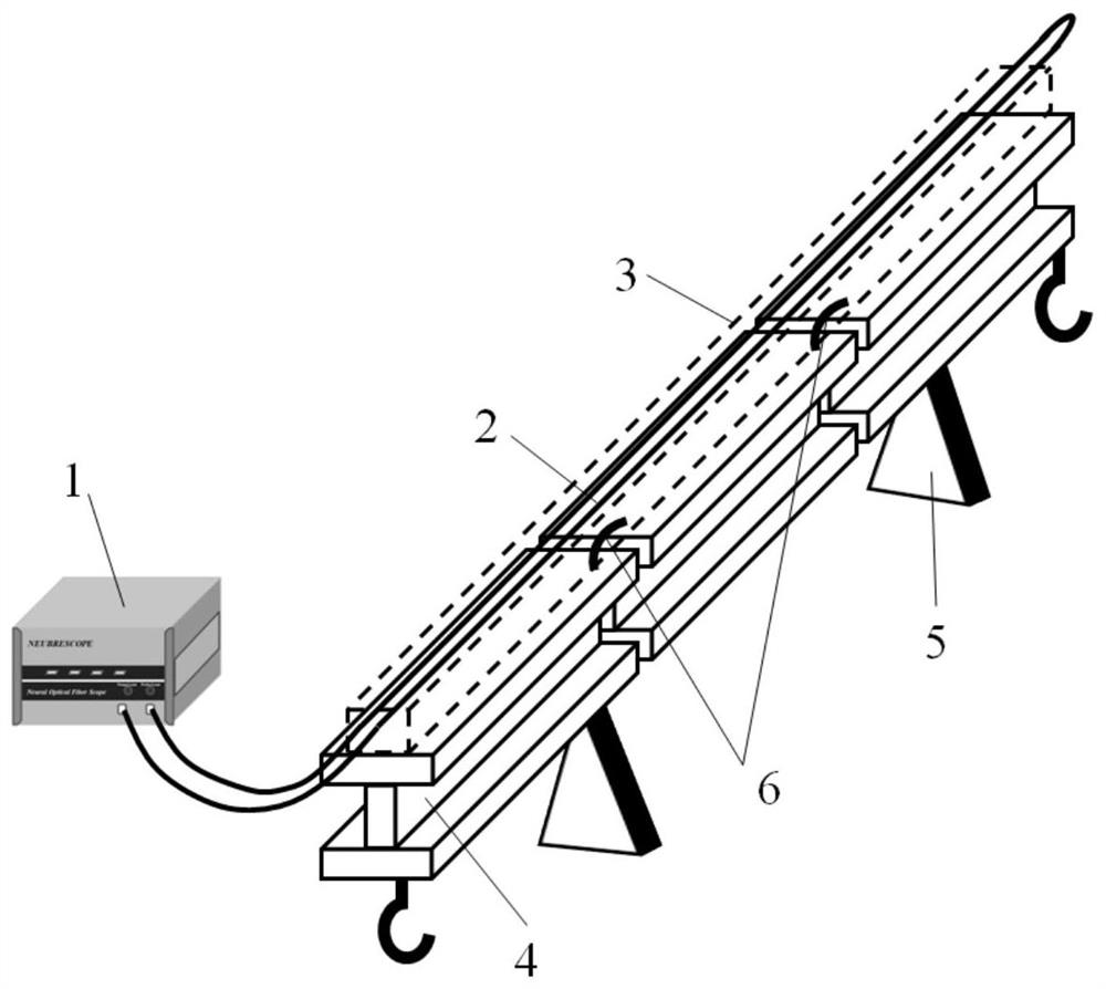
[0028] Such as figure 1 As shown, a distributed optical fiber sensing device capable of monitoring cracks in steel beams includes a sensing fiber 2 to be tested, the sensing fiber 2 to be tested is a photonic crystal fiber, and the outside of the photonic crystal fiber is covered with an epoxy resin adhesive 3 wrapped, pasted on the upper surface of the steel beam 4 along the length direction of the steel beam 4, the photonic crystal fiber is electrically connected to the BOTDA strain analyzer 1, the bottom of the steel beam 4 is provided with a bracket 5, and the bracket 5 supports the steel beam 4 from the bottom; the steel beam 4 Both ends are provided with hooks for hanging iron drums, and sand of different ...


PUM


Abstract

The invention relates to a distributed optical fiber sensing device capable of monitoring a steel beam crack and a monitoring method. The device comprises a sensing optical fiber to be measured, the sensing optical fiber to be measured is a photonic crystal optical fiber, the outer portion of the photonic crystal optical fiber is wrapped by epoxy resin adhesive glue, and the photonic crystal optical fiber is pasted to the upper surface of the steel beam in the length direction of the steel beam; the photonic crystal fiber is electrically connected with a BOTDA strain analyzer, and a bracket is arranged at the bottom of the steel beam; hooks are arranged at two ends of the steel beams; and fiber bragg gratings are arranged at the joints of the steel beams. The photonic crystal fiber is used for replacing a single mode to carry out health monitoring on the steel beam structure, Brillouin gains are two orders of magnitude higher than those in a traditional single-mode fiber, and detection of Brillouin signals is facilitated. Besides, another sensing parameter can be separated from the cladding structure of the photonic crystal fiber and can be used for expanding a new sensing function, and the reliability and the expandability of the detection system are improved.

Description

technical field [0001] The invention belongs to the technical field of structural health monitoring, and in particular relates to a distributed optical fiber sensing device and a monitoring method capable of monitoring steel beam cracks. Background technique [0002] With the planning and construction of a large number of urban infrastructure, my country has become the region with the fastest economic development and the largest construction scale in the world. In this context, people's requirements for the quality of construction projects are constantly improving. Modern engineering is faced with many difficulties, high difficulty and large investment, and the building structure is developing towards super high-rise, large space and long span. Therefore, people's safety requirements are gradually increasing. However, in the building use stage, due to many factors such as stress, fatigue effect, environmental temperature and humidity, aging and corrosion, many safety accid...

Claims


Application Information

Patent Timeline
Patent Type & Authority Applications(China)
IPC IPC(8): G01B11/00G01B11/02
CPCG01B11/00G01B11/02
Inventor 英宇王佳凯
Owner SHENYANG JIANZHU UNIVERSITY
Learn More