
A magnetron sputtering equipment

A technology of magnetron sputtering and equipment, which is applied in the field of magnetron sputtering, can solve problems such as organic light-emitting layer damage, and achieve the effects of reduced damage, ideal coating effect, and high overall sputtering rate

Active Publication Date: 2022-07-12
TCL CHINA STAR OPTOELECTRONICS TECH CO LTD
View PDF3 Cites 0 Cited by
  • Summary
  • Abstract
  • Description
  • Claims
  • Application Information

AI Technical Summary

Problems solved by technology

[0005] Aiming at the deficiencies of the existing technology, the embodiment of the present application provides a magnetron sputtering device, which aims to improve the problem that the existing magnetron sputtering device coats the organic light-emitting layer of the OLED and causes damage to the organic light-emitting layer

Method used


Image

  • A magnetron sputtering equipment
  • A magnetron sputtering equipment
  • A magnetron sputtering equipment

Examples


Embodiment Construction

[0030] The technical solutions in the embodiments of the present application will be clearly and completely described below with reference to the drawings in the embodiments of the present application. Obviously, the described embodiments are only a part of the embodiments of the present invention, but not all of the embodiments. Based on the embodiments of the present invention, all other embodiments obtained by those skilled in the art without creative efforts shall fall within the protection scope of the present invention.

[0031] In the description of the present invention, it should be understood that the terms "upper", "lower", "front", "rear", "left", "right", "vertical", "horizontal", "top", The orientation or positional relationship indicated by "bottom", "inner", "outer", etc. is based on the orientation or positional relationship shown in the accompanying drawings, and is only for the convenience of describing the present invention and simplifying the description, r...


PUM


Abstract

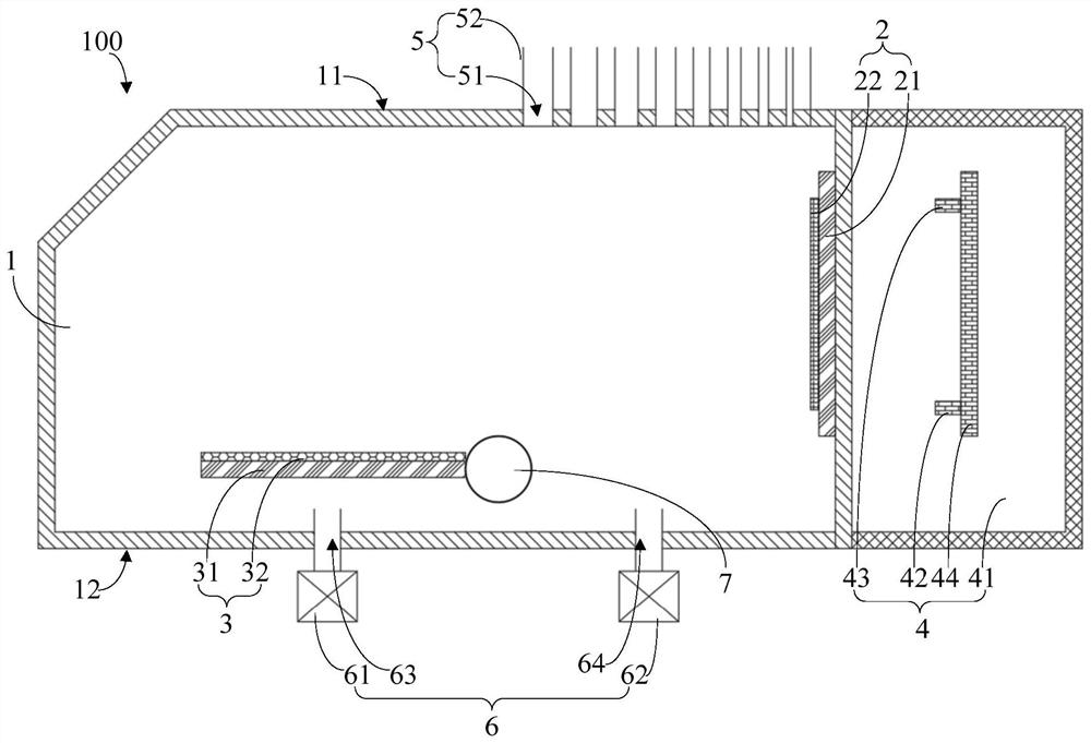
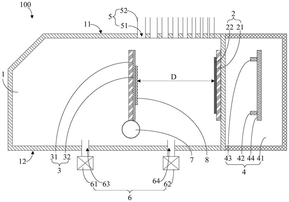
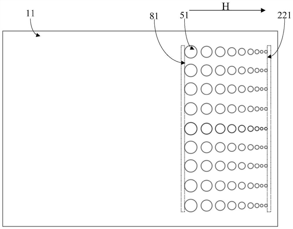
The present application discloses a magnetron sputtering equipment, which mainly includes a sputtering chamber, a cathode part, an anode part, a magnetic pole part and a gas supply part. The cathode part and the anode part are arranged in the sputtering chamber, and the magnetic pole part is used to Electron deflection magnetic field is formed between the anode part and the gas supply part, and the gas supply part is communicated with the sputtering chamber to provide process gas. When the sputtering operation is performed, the cathode part is opposite and parallel to the anode part, in the area between the cathode part and the anode part The process gas concentration in the region near the anode part is higher than that in the region near the cathode part. The magnetron sputtering equipment has the advantages of high overall sputtering rate, ideal coating effect and less damage to the substrate.

Description

technical field [0001] The invention relates to the technical field of magnetron sputtering, in particular to a magnetron sputtering device. Background technique [0002] Magnetron sputtering belongs to a category of physical vapor deposition (Physical Vapor Deposition, PVD) technology. As a coating method, it is widely used in various fields. For example, in the field of microelectronics, magnetron sputtering technology is used to produce integrated circuits and display panels. , one of the important means of thin-film solar cells and other products. In the production process of display panels, magnetron sputtering technology can be used to deposit metal film layers on substrates. The principle of using magnetron sputtering technology to prepare thin films is: under the action of the sputtering power supply, an electric field is formed in the sputtering chamber, and the electric field ionizes the process gas atoms (such as argon atoms) in the sputtering chamber to generate...

Claims


Application Information

Patent Timeline
Patent Type & Authority Patents(China)
IPC IPC(8): C23C14/35H01L51/56
CPCC23C14/35H10K71/00Y02P70/50
Inventor 黄旭
Owner TCL CHINA STAR OPTOELECTRONICS TECH CO LTD
Learn More