Waste heat recovery system, waste heat recovery method and boiler system

A waste heat recovery system and hot end technology, applied in heating systems, heating methods, preheating, etc., can solve problems such as rust, blocked air duct smoke exhaust, and easy corrosion of heat exchangers.

Pending Publication Date: 2021-06-01
SHANGHAI DONGRUN HEAT EXCHANGE EQUIP MFG
View PDF0 Cites 1 Cited by
  • Summary
  • Abstract
  • Description
  • Claims
  • Application Information

AI Technical Summary

Problems solved by technology

[0005] The purpose of the present invention is to provide a waste heat recovery system to solve the technical problems that the heat exchanger is easy to corrode, rust, and ash blockage in the traditional waste heat recovery without increasing the cost; The purpose is also to provide a boiler system using the above-mentioned waste heat recovery system; the purpose of the present invention is to provide a technical problem that can solve the traditional waste heat recovery, where the heat exchanger is easy to corrode, rust, and ash clogging leads to the obstruction of air duct smoke exhaust waste heat recovery method

Method used


Image

  • Waste heat recovery system, waste heat recovery method and boiler system
  • Waste heat recovery system, waste heat recovery method and boiler system
  • Waste heat recovery system, waste heat recovery method and boiler system

Examples


Embodiment 1

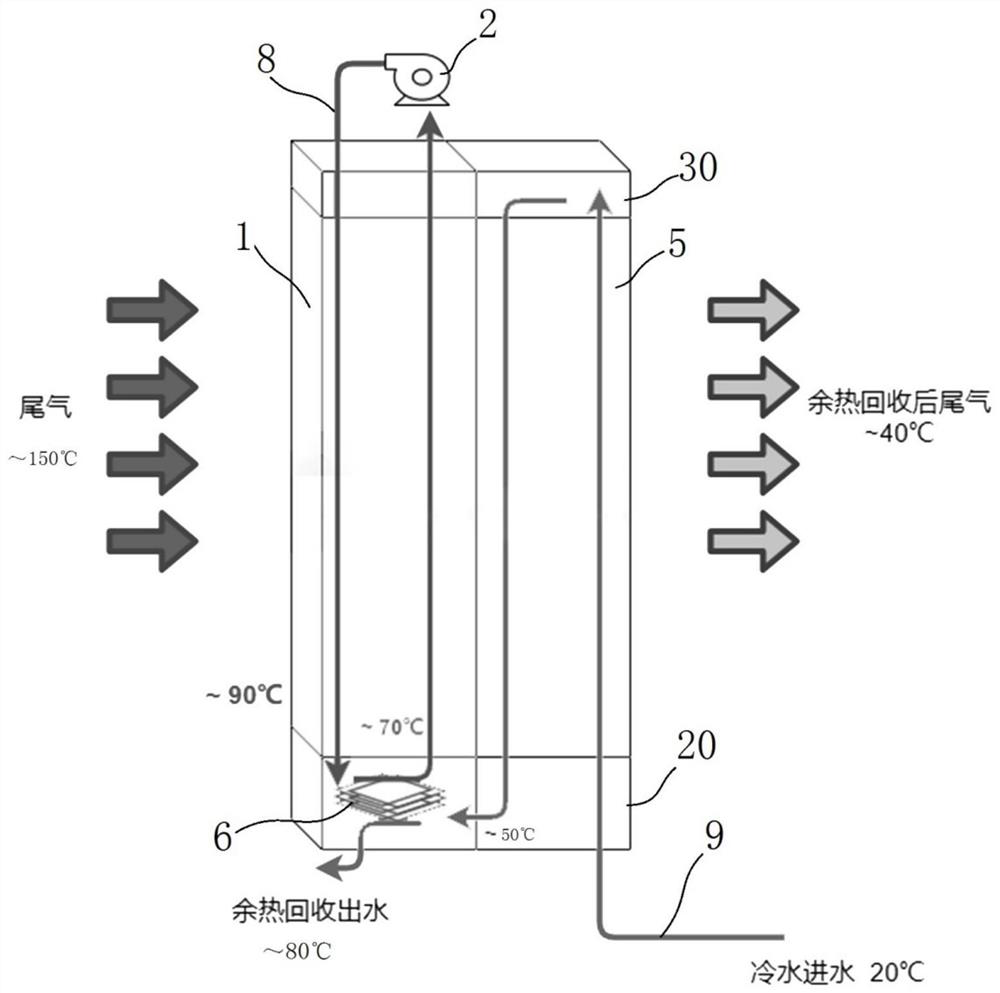
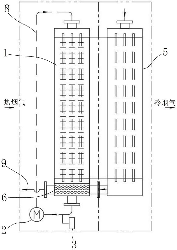
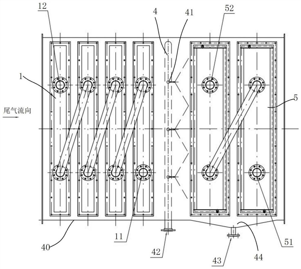
[0051] The waste heat recovery system is used to recover waste heat from the exhaust gas of gas-fired boilers or coal-fired boilers. It has a shell 40, which is pipe-shaped and connected in series in the exhaust gas pipeline, that is, the two ends are respectively sealed and docked with the exhaust gas pipe, so that the boiler The exhaust gas can pass through the waste heat recovery system. After heat exchange, the exhaust gas is discharged. The heat in the exhaust gas is transferred to the heat transfer medium of the waste heat recovery system, and the heat of the heat transfer medium is used for heating, etc., to realize the secondary use of heat.

[0052]The waste heat recovery system includes: a first heat exchanger, which is arranged in the flue, and has a first internal pipeline, and the first internal pipeline is filled with a first heat exchange medium, and the temperature of the first heat exchange medium is higher than that of the water in the flue gas The dew point t...

Embodiment 2

[0080] Embodiment 2 of the waste heat recovery system of the present invention: as Figure 5 As shown, the difference from Example 1 is that a fourth heat exchanger 7 is also provided after the second heat exchanger 5 to solve the whitening problem, specifically: the fourth heat exchanger 7 is an empty water exchange Heater, since there is basically no condensation here, it is also possible to use a heat exchanger made of ordinary carbon steel + galvanized to reduce costs. The heat exchange medium in the fourth heat exchanger 7 is the second heat exchange medium 9, That is, part of the second heat exchange medium 9 is introduced into the fourth heat exchanger 7 after heat exchange in the third heat exchanger 6, so as to realize the reverse heating of the exhaust gas, referred to as recuperation, and the exhaust gas can be reheated after reheating Whitening effect.

[0081] The working principle of whitening here is as follows: After passing through the second heat exchanger 5...


PUM


Abstract

The invention relates to a waste heat recovery system, a waste heat recovery method and a boiler system, and solves the technical problem that smoke exhaust of an air duct is blocked due to the fact that a heat exchanger is prone to corrosion, rusting and dust blockage during traditional waste heat recovery on the premise that cost is not increased too much. The waste heat recovery system comprises a tubular shell connected to a flue in series, and a first heat exchanger and a second heat exchanger which are arranged in the shell, wherein the temperature of a first heat exchange medium is higher than the dew point temperature of water vapor condensed on the outer surface of the first heat exchanger in the flue gas; the first heat exchanger is a finned tube heat exchanger made of common carbon steel; the second heat exchanger is located on the downstream of the first heat exchanger in the flue gas flowing direction, a second internal pipeline is arranged in the second heat exchanger and provided with a cooling water inlet and a cooling water outlet, the cooling water inlet is connected to a water supply system for supplying a second heat exchange medium, the second heat exchange medium exchanges heat with the flue gas for the second time in the second internal pipeline, a large amount of water vapor in the flue gas is condensed on the outer surface of the second heat exchanger; and the second heat exchanger is a tube heat exchanger made of a high-corrosion-resistance material.

Description

technical field [0001] The invention relates to a waste heat recovery system, a waste heat recovery method and a boiler system. Background technique [0002] With the continuous deepening of my country's energy-saving and emission-reduction policies, the original coal-fired boilers that provide steam for enterprises or residents are gradually replaced by gas-fired boilers fueled by natural gas. Taking an industrial park as an example, 3 gas-fired boilers can generate 150 steam per hour. tons, its consumption capacity is huge, and the temperature of the exhaust gas after combustion is around 110-150°C. The main component of natural gas is methane CH4. According to its combustion chemical formula: CH4+2O2=CO2+2H2O, 1m 3 After the natural gas is fully burned, the calorific value is about 35.88MJ without considering the condensation. When considering the condensation heat release, because the water vapor will release a lot of heat when it condenses, the calorific value can be as...

Claims


Application Information

Patent Timeline
Patent Type & Authority Applications(China)
IPC IPC(8): F22D1/00F23J15/06F24D15/00F28F19/00F28F19/06F28F19/02
CPCF22D1/003F23J15/06F24D15/00F24D2200/18F28F19/00F28F19/02F28F19/06Y02E20/30
Inventor 茅思远石印涛周德望顾惠玲
Owner SHANGHAI DONGRUN HEAT EXCHANGE EQUIP MFG
Why Eureka
Try Eureka