Diffusion welding lamination defect ultrasonic detection test block as well as preparation method and application thereof

A technology of ultrasonic testing and diffusion welding, applied in the field of diffusion welding, can solve the problems of difficulty in ensuring dimensional accuracy, difficulty in ensuring position accuracy, and difficulty in forming test blocks, and achieves the effect of improving the detection effect, the detection accuracy, and the detection accuracy.

Active Publication Date: 2021-06-01
NORTHWESTERN POLYTECHNICAL UNIV
View PDF7 Cites 0 Cited by
  • Summary
  • Abstract
  • Description
  • Claims
  • Application Information

AI Technical Summary

Problems solved by technology

[0005] However, the existing methods for preparing test blocks have the following defects: (1) Since the diffusion welding defects exist inside the joint, that is, at the position of the diffusion welding interface, and the scale is micron, it is difficult to guarantee the position accuracy by traditional machining methods , it is more difficult to ensure the dimensional accuracy, that is, it is difficult to realize the processing of internal micron-scale artificial reflectors
(2) Surface turning The method of processing threads on the surface to be welded can realize defect prefabrication at the diffusion welding interface, but it is difficult to guarantee the dimensional accuracy, and the shape is uneven, so it is difficult to form a test block
(3) The existing multi-layer defect prefabrication method can only produce macro-defects, but cannot realize the prefabrication of multi-layer micron-scale defects by diffusion welding, and there is no combination of upper and lower layer defects, so it is difficult to form a test block

Method used


Image

  • Diffusion welding lamination defect ultrasonic detection test block as well as preparation method and application thereof
  • Diffusion welding lamination defect ultrasonic detection test block as well as preparation method and application thereof
  • Diffusion welding lamination defect ultrasonic detection test block as well as preparation method and application thereof

Examples


Embodiment 1

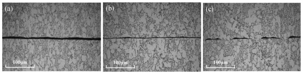
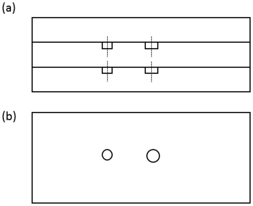
[0053] This embodiment provides a method for preparing a test block for ultrasonic detection of diffusion welding laminate defects, such as figure 2 shown, including:

[0054] (1) Substrate defect processing

[0055] Three substrates (TC4 boards) were taken, one of which was used as a cover plate without defect processing, and the other two substrates were machined with milling cutters of different processing sizes to process slot-like defects with widths of 80 μm, 100 μm, 150 μm and 200 μm, respectively. The distance between the centers of two adjacent defect grooves is 5mm.

[0056] (2) Substrate surface treatment

[0057] Clean the surface to be welded at the non-defect position of the substrate to ensure the welding quality, as follows: firstly, the surface is polished step by step with sandpaper, and the surface is polished to a mirror surface with a polishing solution (silica sol:hydrogen peroxide=10:1) Maintain parallelism. Use Keller reagent (1ml HF+1.5ml HCl+2.5m...

Embodiment 2

[0063] This embodiment provides a method for preparing a test block for ultrasonic detection of diffusion welding laminate defects, such as figure 2 shown, including:

[0064] (1) Substrate defect processing

[0065] Three substrates (TC4 boards) were taken, one of which was used as a cover plate without defect processing, and the other two substrates were machined with milling cutters of different processing sizes to process slot-like defects with widths of 70 μm, 90 μm, 140 μm and 190 μm, respectively. The distance between the centers of two adjacent defect grooves is 4mm.

[0066] (2) Substrate surface treatment

[0067] Clean the surface to be welded on the non-defective position of the substrate to ensure the welding quality, as follows: firstly, the surface is polished step by step with sandpaper, and the surface is polished to a mirror surface with a polishing solution (silica sol: hydrogen peroxide = 9:1). Maintain parallelism. Use Keller reagent (1ml HF+1.5ml HCl...

Embodiment 3

[0073] This embodiment provides a method for preparing a test block for ultrasonic detection of diffusion welding laminate defects, such as figure 2 shown, including:

[0074] (1) Substrate defect processing

[0075] Three substrates (TC4 board) were taken, one of the substrates was used as a cover plate without defect processing, and the other two substrates were machined with milling cutters of different processing sizes. The distance between the centers of two adjacent defect grooves is 6mm.

[0076] (2) Substrate surface treatment

[0077] Clean the surface to be welded on the non-defective position of the substrate to ensure the welding quality, as follows: firstly, the surface is polished step by step with sandpaper, and the surface is polished to a mirror surface with a polishing solution (silica sol: hydrogen peroxide = 11:1). Maintain parallelism. Use Keller reagent (1ml HF+1.5ml HCl+2.5ml HNO) before welding and assembly 3 +95ml H 2 O) Pickle the sample to be ...


PUM


Abstract

The invention discloses a diffusion welding lamination defect ultrasonic detection test block as well as a preparation method and application thereof, and relates to the technical field of diffusion welding. The diffusion welding lamination defect ultrasonic detection test block is formed by performing diffusion welding on multiple layers of substrates which are assembled in a stacked mode from top to bottom, defect grooves are formed in diffusion welding interface positions between every two adjacent layers of substrates, and the defect grooves located in the upper layer and the adjacent defect grooves located in the lower layer are in a crossed state. The defect grooves in the crossed state are used for forming the assembly, and the assembly of multiple sizes of micron-sized defects with overlapped upper and lower layers can be formed, so that the detection capability of the micron-sized defects on the lower layer can be researched under the influence of micron-sized defect signals on the upper layer. And meanwhile, a single-layer defect which does not have an intersection part and does not have upper and lower layer overlapping can be used as a reference defect. The detection precision of the lower-layer micron-sized defects when multiple layers of defects are overlapped is improved, and the detection effect of multi-layer diffusion welding defect detection is improved.

Description

technical field [0001] The invention relates to the technical field of diffusion welding, in particular to a test block for ultrasonic detection of diffusion welding lamination defects, a preparation method and application thereof. Background technique [0002] In order to ensure the accuracy, repeatability and comparability of the test results in ultrasonic testing, a sample with known fixed characteristics must be used to calibrate the testing system. This kind of sample with a simple geometric shape artificial reflector or simulated defect designed and manufactured according to a certain purpose is usually called a test block, and the test block for ultrasonic testing is usually divided into a standard test block, a comparison test block and a simulation test block. The artificial reflector in the test block is selected according to its purpose, and it should be as close as possible to the defect characteristics to be detected. Usually, the required shape and size are pro...

Claims


Application Information

Patent Timeline
IPC IPC(8): G01N29/30
CPCG01N29/30
Inventor 宋慧熊江涛尹小康李京龙宋文清
Owner NORTHWESTERN POLYTECHNICAL UNIV
Why Eureka
Try Eureka