Integrated electromagnetic coupling mechanism and electric energy transmitting end, receiving end and transmission system thereof

An electric energy transmission system and electromagnetic coupling technology, applied in the field of electromagnetic coupling, can solve the problems of increased system volume and weight, reduced system power density, increased system cost, etc., to increase the electric field coupling coefficient, reduce ohmic loss, and overcome the impact Effect

Active Publication Date: 2021-06-01
CHONGQING UNIVERSITY OF SCIENCE AND TECHNOLOGY
View PDF9 Cites 0 Cited by
  • Summary
  • Abstract
  • Description
  • Claims
  • Application Information

AI Technical Summary

Problems solved by technology

[0010] The present invention provides an integrated electromagnetic coupling mechanism and its electric energy transmitting end, receiving end and transmission system. The technical problem to be solved is: for a single electric field coupling mechanism, The introduction of Litz coils and high-order compensation networks in the prior art leads to increased system volume and weight, increased system cost, and greatly reduces system power density

Method used


Image

  • Integrated electromagnetic coupling mechanism and electric energy transmitting end, receiving end and transmission system thereof
  • Integrated electromagnetic coupling mechanism and electric energy transmitting end, receiving end and transmission system thereof
  • Integrated electromagnetic coupling mechanism and electric energy transmitting end, receiving end and transmission system thereof

Examples


Embodiment 1

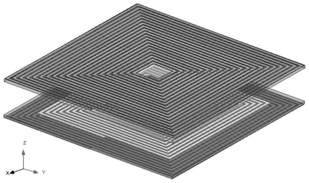
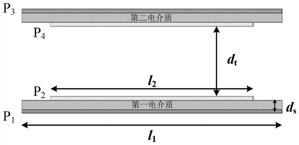
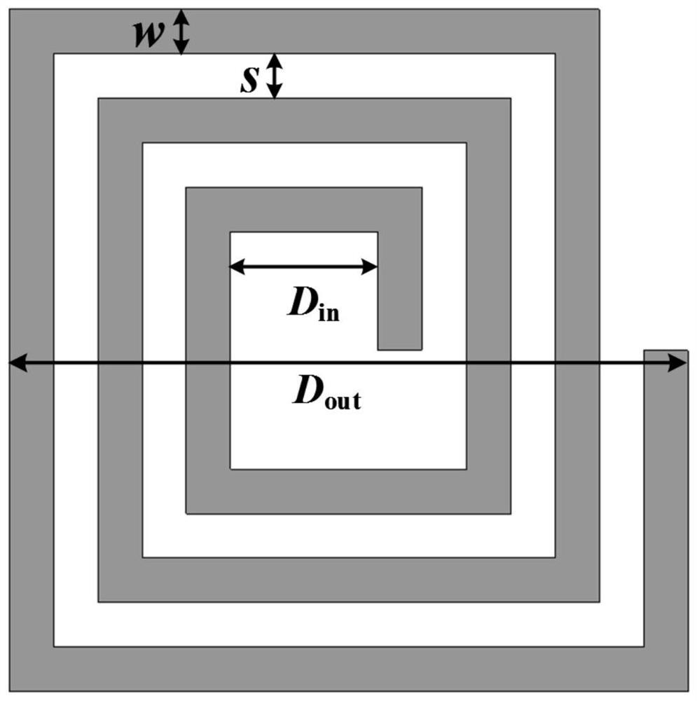
[0051] An integrated electromagnetic coupling mechanism provided by an embodiment of the present invention, such as Figure 1~3 As shown, in this embodiment, it is different from the coils wound with Litz wire in the previous research on the IPT system, and it is also different from the use of metal plates as electrodes in the previous research on the CPT system. The electromagnetic poles in this embodiment use a Square metal wires of a certain width (copper foil strips are used in this embodiment) are spirally wound, which can not only ensure the self-inductance value of the coil itself and the mutual inductance value between the coils, but also increase the cross-coupling capacitance between the electromagnetic poles , to increase the electric field coupling coefficient, and to improve the quality of power transmission by making full use of the coil parasitic capacitance characteristics that were neglected in previous studies. in figure 1 The three-dimensional diagram of th...

Embodiment 2

[0055] 1. System circuit model and its equivalent simplification

[0056] This embodiment provides a power transmission system with an integrated electromagnetic coupling mechanism. In order to save cost and simplify the circuit, this embodiment utilizes the capacitance and inductance characteristics of the integrated electromagnetic coupling mechanism described in the embodiment, and adopts a non-compensated structure. At the same time, in order to further simplify the system structure, a half-bridge inverter circuit is used, such as Figure 5 As shown, the first inner electromagnetic pole P of the stacked coupling mechanism in the figure 2 The terminal with the same name is connected to the high potential terminal of the inverter output, the first external electromagnetic pole P 1 The opposite end of the inverter is connected to the low potential end of the inverter output to reduce leakage electric field radiation.

[0057] In order to simplify the analysis, this embodim...

Embodiment 3

[0129] Based on Embodiment 2, this embodiment provides a power transmitting end of an integrated electromagnetic coupling mechanism, which can be installed in a power transmitting device, and is provided with a half-bridge inverter circuit and an electromagnetic pole at the transmitting end. The half-bridge inverter circuit That is, the half-bridge inverter circuit in the system described in Embodiment 2 is adopted, and the electromagnetic pole at the transmitting end adopts the first outer electromagnetic pole P described in Embodiment 2. 1 , the first inner electromagnetic pole P 2 , while about the first outer electromagnetic pole P 1 , the first inner electromagnetic pole P 2 More specific parameter design can be consistent with Embodiment 2, and can also be set according to specific application requirements.

[0130] It should be noted that the power transmitting device, equipment, etc. including the power transmitting end are also included in the implementation scope o...


PUM


Abstract

The invention relates to the technical field of electromagnetic coupling, and particularly discloses an integrated electromagnetic coupling mechanism and an electric energy transmitting end, receiving end and transmission system thereof; the coupling mechanism comprises a first outer magnetic pole P1, a first dielectric medium and a first inner electromagnetic pole P2 which are stacked, and a second inner electromagnetic pole P4, a second dielectric medium and a second outer magnetic pole P3 which are stacked, the first inner electromagnetic pole P2 and the second inner electromagnetic pole P4 are opposite to each other, and the distance between the first inner electromagnetic pole P2 and the second inner electromagnetic pole P4 is dt. The electromagnetic poles P1, P2, P4 and P3 are all formed by spirally winding square metal lines with the same specification in the same direction. According to the electric energy transmission system provided by the invention, on the basis of the integrated electromagnetic coupling mechanism, a circuit theory and a mutual inductance coupling theory, an equivalent circuit of the coupling mechanism is simplified, a system alternating current impedance model is established, and the self-compensation of the coupling mechanism is realized by analyzing and calculating a relationship among electric parameters of the coupling mechanism; and the working condition of the zero input impedance angle of the system is given.

Description

technical field [0001] The present invention relates to the technical field of electromagnetic coupling, in particular to an integrated electromagnetic coupling mechanism, an electric energy transmitting end of an integrated electromagnetic coupling mechanism, an electric energy receiving end of an integrated electromagnetic coupling mechanism and an integrated electromagnetic coupling mechanism Power transmission system. Background technique [0002] Wireless Power Transfer (WPT) is a power transmission technology that comprehensively utilizes power electronics technology and modern control theory and realizes no direct electrical contact through soft media (magnetic field, electric field, microwave and laser, etc.). It solves the problem of unsafe and inflexible access to electric energy in the traditional electrical equipment contact power supply mode. At present, the most widely studied are Magnetic-field Coupled Wireless Power Transfer (MC-WPT) and Electric-field Coupl...

Claims


Application Information

Patent Timeline
Patent Type & Authority Applications(China)
IPC IPC(8): H02J50/10H02J50/12H02J50/05
CPCH02J50/10H02J50/12H02J50/05H02J50/005
Inventor 吴学颖宋乐鹏黄超张俊林李语燕陈文斌刘峰佚
Owner CHONGQING UNIVERSITY OF SCIENCE AND TECHNOLOGY
Why Eureka
Try Eureka