
Industrial chemical pipeline manufacturing and machining method

A technology for chemical pipelines and processing methods, which is applied to manufacturing tools, metal processing equipment, auxiliary devices, etc., can solve the problems of reducing the quality of welding connections, prone to sliding, and low degree of fixation, and achieves expansion of the scope of application and tightness of fit. Avoid and improve the effect of stability

Active Publication Date: 2021-06-04
任波
View PDF0 Cites 0 Cited by
  • Summary
  • Abstract
  • Description
  • Claims
  • Application Information

AI Technical Summary

Problems solved by technology

[0003] 1. The overall connection between the flange and the pipeline is less fixed, so that the relative deflection phenomenon is more likely to occur in the welded rib plate and the quality of the welded connection is reduced. At the same time, the fixed structure is very important for the flange size and The adaptability to changes in the diameter of the pipe is low;
[0004] 2. The tightness of the connection between the rib plate and the flange plate and the pipe is relatively low, and the sliding phenomenon between the rib plate and the flange plate, and between the rib plate and the pipe is easy to occur, which seriously affects the smooth progress of the welding operation and the Reduce the quality of welding connection, and the structure with the function of clamping ribs is mostly suitable for ribs with a single thickness size

Method used


Image

  • Industrial chemical pipeline manufacturing and machining method
  • Industrial chemical pipeline manufacturing and machining method
  • Industrial chemical pipeline manufacturing and machining method

Examples


Embodiment Construction

[0041] The embodiments of the present invention will be described in detail below in conjunction with the accompanying drawings, but the present invention can be implemented in various ways defined and covered by the claims.

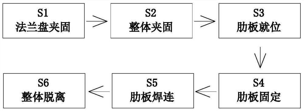
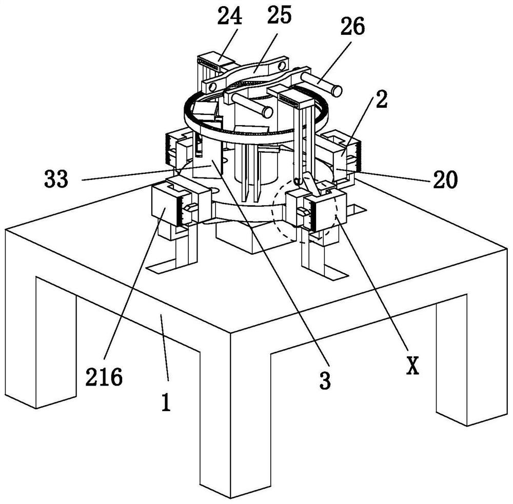
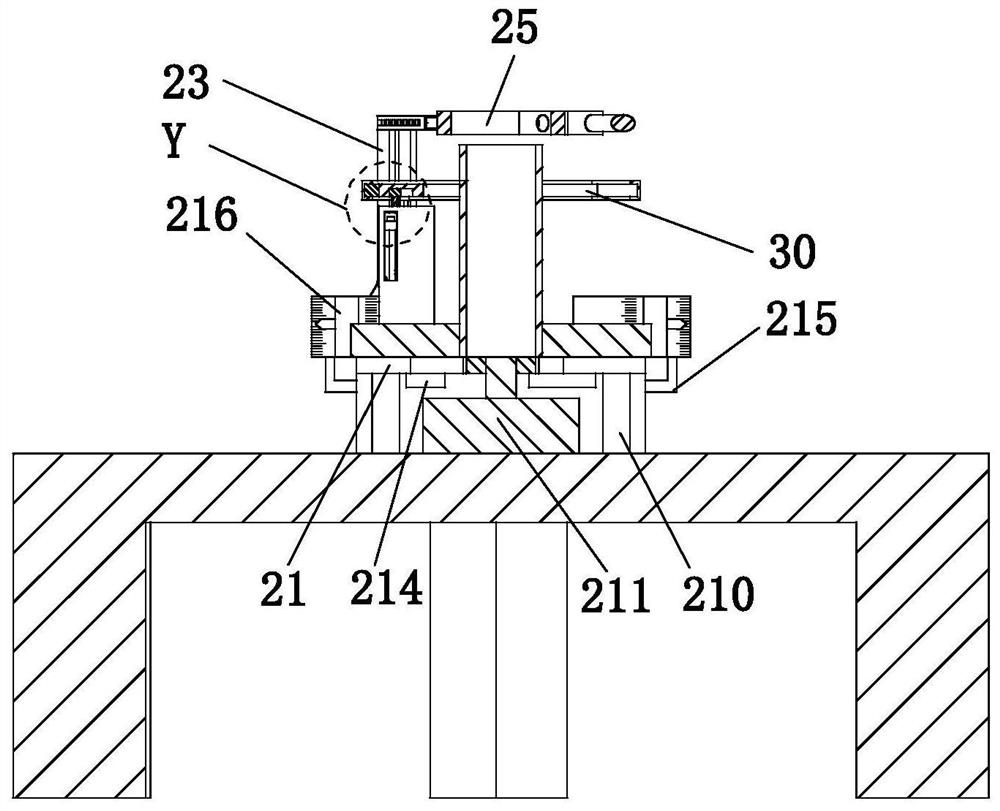
[0042] like Figure 1 to Figure 11 An industrial chemical pipeline manufacturing and processing method is shown, which uses an industrial chemical pipeline manufacturing and processing device. The industrial chemical pipeline manufacturing and processing device includes a workbench 1, a clamping mechanism 2 and an auxiliary welding unit 3, and adopts industrial chemical pipeline manufacturing and processing. The specific processing methods of the device for industrial chemical pipeline manufacturing and processing are as follows:

[0043] S1. Flange clamping: the flange is placed on the support plate 21 by manual means, and the lower splint 20 performs clamping treatment around it;

[0044] S2. Overall clamping: the connecting plate 23 is pressed down m...


PUM


Abstract

The invention relates to an industrial chemical pipeline manufacturing and machining method. An industrial chemical pipeline manufacturing and machining device is used in the industrial chemical pipeline manufacturing and machining method, the industrial chemical pipeline manufacturing and machining device comprises a workbench, a clamping and fixing mechanism and an auxiliary welding unit, the clamping and fixing mechanism is arranged at the upper end of the workbench, and the auxiliary welding unit is arranged at the upper end of the clamping and fixing mechanism. According to the industrial chemical pipeline manufacturing and machining method, the design concept of combining multiple regulation and control structures is adopted to manufacture and a machine industrial chemical pipeline, the arranged clamping and fixing mechanism can implement linkage multi-directional clamping and fixing treatment between a flange plate and the pipeline, so that the overall stability degree of the flange plate and the pipeline is improved to achieve the purpose of reducing the influence on the subsequent rib plate welding and connecting effect; and the arranged auxiliary welding unit has the functions of improving the attaching tightness degree between the rib plate and the flange plate and the attaching tightness degree between the rib plate and the pipeline and preventing the rib plate from sliding, and therefore the welding and connecting quality between the rib plate and the flange plate and the welding and connecting quality between the rib plate and the pipeline can be improved.

Description

technical field [0001] The invention relates to the field of pipeline processing, in particular to an industrial chemical pipeline manufacturing and processing method. Background technique [0002] The main material of steel-plastic chemical pipes is ultra-high molecular weight polyethylene. Ultra-high molecular weight polyethylene is a thermoplastic engineering plastic polymerized by ethylene and butadiene monomers under the action of a catalyst. Chemical pipes need to be used during processing or installation. The flanges are connected to each other or to other structures. At the same time, the connection between the pipe and the flange needs to be externally fixed according to the installation requirements. The comprehensive performance of the chemical pipeline is superior, and it is wear-resistant, low-temperature resistant, and durable. Corrosion, self-lubrication, and impact resistance are the highest among all plastics. The wear resistance is better than polytetrafluo...

Claims


Application Information

Patent Timeline
IPC IPC(8): B23K31/02B23K37/04
CPCB23K31/02B23K37/0461B23K37/0435
Inventor 任波刘文琴
Owner 任波
Learn More