

Large-scale high-speed rotation equipment assembly stress measurement method based on critical refraction longitudinal waves
A technology of critical refraction and assembly stress, which is applied to force/torque/work measuring instruments, measuring devices, and the use of sound waves/ultrasonic waves/infrasonic waves to analyze solids, etc., which can solve the problem that the spatial resolution of signal separation cannot be guaranteed at the same time, rotor surface corrosion, measurement Low efficiency and other problems, achieve the effect of multi-point scanning measurement, eliminate corrosion and pollution, and improve measurement efficiency
- Summary
- Abstract
- Description
- Claims
- Application Information
AI Technical Summary
Problems solved by technology
Method used
Image

Examples
specific Embodiment approach 1
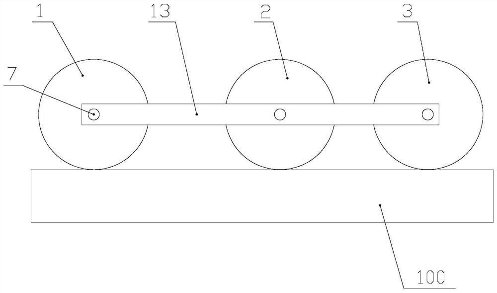
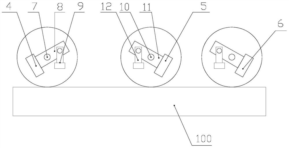
[0032] Specific implementation mode one: combine figure 1 and figure 2 Describe this embodiment, the large-scale high-speed rotary equipment assembly stress measurement method based on the critical refraction longitudinal wave, it adopts the measurement device to realize, and the measurement device includes the transmitting wheel 1 arranged side by side, the first receiving wheel 2, the second receiving wheel 3 and the installation The transmitting transducer 4 inside the transmitting wheel 1, the first receiving transducer 5 installed in the first receiving wheel 2 and the second receiving transducer 6 installed in the second receiving wheel 3, the transmitting wheel 1, The axes of the first receiving wheel 2 and the second receiving wheel 3 are arranged parallel to each other;
[0033] The measurement method includes the following steps:
[0034] Step 1. According to the material properties of the rotor part 100, adjust the inclination angles of the transmitting transduce...
PUM
 Abstract
Description
Claims
Application Information