High-speed modulator

A modulator, high-speed technology, applied in instruments, nonlinear optics, optics, etc., can solve the problems of difficulty in reducing the length of the device, reducing the modulation bandwidth of the device, and small device size.

Pending Publication Date: 2021-06-04
HUAZHONG UNIV OF SCI & TECH
View PDF8 Cites 6 Cited by
  • Summary
  • Abstract
  • Description
  • Claims
  • Application Information

AI Technical Summary

Problems solved by technology

[0005] In fact, although the method of increasing the length of the modulation arm of the modulator will reduce the modulation bandwidth of the device to a certain extent, and can effectively reduce the half-wave voltage to less than 1.5V, the result of this is that the length of the device is less than 2 cm. above, unless future in the half-wave voltage-length product value (V π L) has a large reduction, otherwise the length of the device will be difficult to have a large reduction
However, the excessive device length will make this type of device encounter great difficulties in the process of commercialization, and the size of the device will become a difficult problem to be solved in the process of packaging.
[0006] To sum up, it is difficult for today's MZ modulators to maintain a small device size while achieving a low half-wave voltage, and there is an urgent need for a high-speed modulator that simultaneously achieves a low half-wave voltage and a smaller size on-chip.

Method used


Image

  • High-speed modulator
  • High-speed modulator
  • High-speed modulator

Examples


Embodiment 1

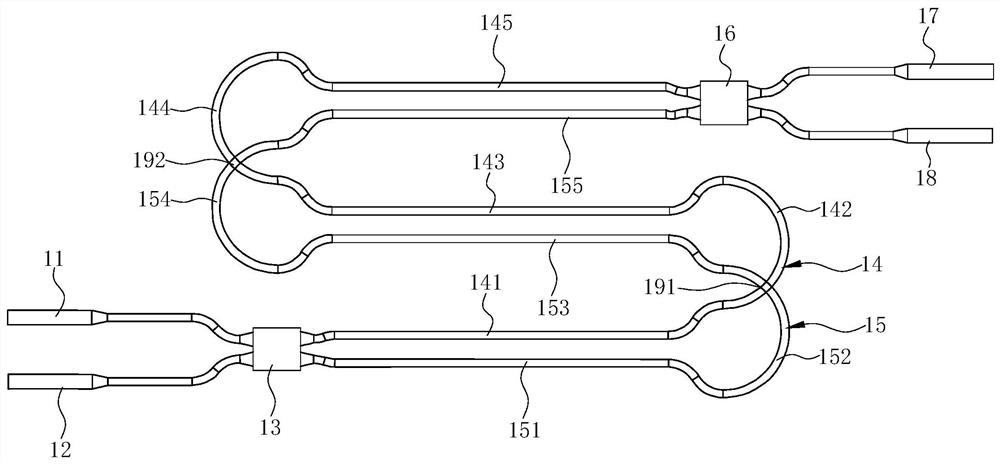
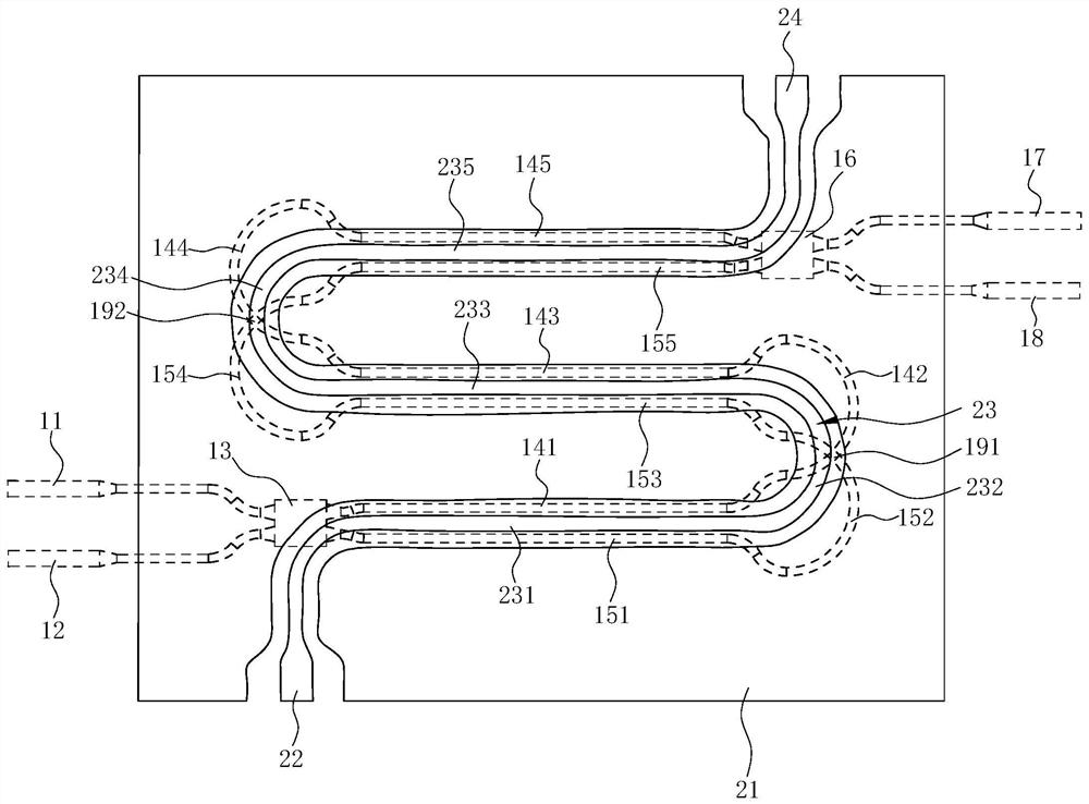
[0024] see Figure 1 ~ Figure 3 , a high-speed modulator, which includes an optical waveguide structure and a traveling-wave electrode structure, and the optical waveguide structure is in figure 2 shown in dotted line.

[0025] Wherein, the optical waveguide structure includes a first input optical waveguide 11, a second input optical waveguide 12, a first beam splitter 13, a first optical waveguide arm 14, a second optical waveguide arm 15, a second beam splitter 16, a first An output optical waveguide 17 and a second output optical waveguide 18 . The first input optical waveguide 11 and the second input optical waveguide 12 serve as the input ends of the optical waveguide structure, and the first output optical waveguide 17 and the second output optical waveguide 18 serve as the output ends of the optical waveguide structure. The beam splitter may be a multimode interference coupler.

[0026] Wherein, both the first beam splitter 13 and the second beam splitter 16 are 2×...

Embodiment 2

[0047] see Figure 4 and Figure 5 , the difference from the first embodiment above is that the positions of the first optical waveguide arm 14 and the second optical waveguide arm 15 are exchanged during the extension process, that is, the first bending arm 142 and the third bending arm 152 are arranged side by side. , the second curved arm 144 and the fourth curved arm 154 are arranged side by side, the curved arc length (including radius) of the first curved arm 142 is smaller than the third curved arm 152, and the curved arc length (including radius) of the second curved arm 144 is larger than The fourth curved arm 154 . As a result, the first optical waveguide arm 14 and the second optical waveguide arm 15 no longer have intersections, and the two always keep extending side by side. Figure 4 From bottom to top, there are the fourth straight arm 151 , the first straight arm 141 , the second straight arm 143 , the fifth straight arm 153 , the sixth straight arm 155 and t...


PUM

PropertyMeasurementUnit
thicknessaaaaaaaaaa
thicknessaaaaaaaaaa
thicknessaaaaaaaaaa

Abstract

The present invention discloses a high-speed modulator which comprises an optical waveguide structure and a traveling wave electrode structure, the optical waveguide structure comprises a first optical waveguide arm and a second optical waveguide arm, a traveling wave electrode comprises a grounding electrode and a signal line, and the signal line applies electric fields or voltages in opposite directions to the first optical waveguide arm and the second optical waveguide arm. The first optical waveguide arm and the second optical waveguide arm are both of a folding structure, and the signal line is folded along with the first optical waveguide arm and the second optical waveguide arm, so that an electric field or voltage applied to the first optical waveguide arm and the second optical waveguide arm is kept unchanged. Or the electric field or the voltage applied to the first optical waveguide arm and the second optical waveguide arm is synchronously changed. Compared with the prior art, the device has the advantages that the folding structure of the optical waveguide is matched with the ground-signal-ground coplanar waveguide traveling wave electrode structure, modulation addition of light in different sections of the waveguide is achieved, the longer phase shift waveguide length can be achieved within the limited device length, and meanwhile it can be ensured that the bandwidth meets the application requirement.

Description

technical field [0001] The invention relates to an optical component, especially a high-speed modulator. Background technique [0002] With the continuous development of optical communication systems, the requirements for the transmission rate of optical communication are constantly increasing, and the performance requirements for modulators are also getting higher and higher. The performance of traditional directly modulated lasers or electro-absorption modulated lasers can meet short-to-middle-distance data transmission, but it is difficult to make breakthroughs in ultra-long-distance and ultra-high transmission rate signal transmission. Therefore, the Mach-Zehnder based on phase modulation (MZ) modulators become the obvious choice for this generation and even the next generation of ultra-high performance modulators. Commercially available high-speed MZ modulators today include traditional bulk lithium niobate modulators, silicon optical modulators, and indium phosphide-b...

Claims


Application Information

Patent Timeline
Patent Type & Authority Applications(China)
IPC IPC(8): G02F1/03G02F1/035
CPCG02F1/0305G02F1/0316G02F1/035
Inventor 国伟华刘晔陆巧银
Owner HUAZHONG UNIV OF SCI & TECH
Why Eureka
Try Eureka