Broadband directional dipole antenna for ground penetrating radar

A dipole antenna, ground penetrating radar technology, applied in the direction of antenna, electromagnetic wave detection, antenna grounding switch structure connection, etc., can solve the problem that dipole antenna cannot meet the performance requirements of ground penetrating radar antenna, dipole antenna Narrow bandwidth, no directional radiation and other issues, to achieve the effect of radiating transient pulses, satisfying detection distance and resolution, and small fluctuations

Pending Publication Date: 2021-06-04
BC P INC CHINA NAT PETROLEUM CORP +1
View PDF5 Cites 4 Cited by
  • Summary
  • Abstract
  • Description
  • Claims
  • Application Information

AI Technical Summary

Problems solved by technology

[0005] Aiming at the problem that the dipole antenna has a narrow working bandwidth and does not have the characteristics of directional radiation, so that the conventional dipole antenna cannot meet the requirements of the antenna performance of the ground penetrating radar, the present invention provides a broadband directional dipole for ground penetrating radar Pole antenna, the antenna working frequency is 140MHz~250MHz, the center frequency point is 195MHz, the time domain waveform has high fidelity, the amplitude ratio of the front and rear radiation waveforms is greater than 10dB, and the thickness is not greater than 13cm

Method used


Image

  • Broadband directional dipole antenna for ground penetrating radar
  • Broadband directional dipole antenna for ground penetrating radar
  • Broadband directional dipole antenna for ground penetrating radar

Examples


Embodiment Construction

[0027] The present invention will be further described in detail below in conjunction with the accompanying drawings, which are explanations rather than limitations of the present invention.

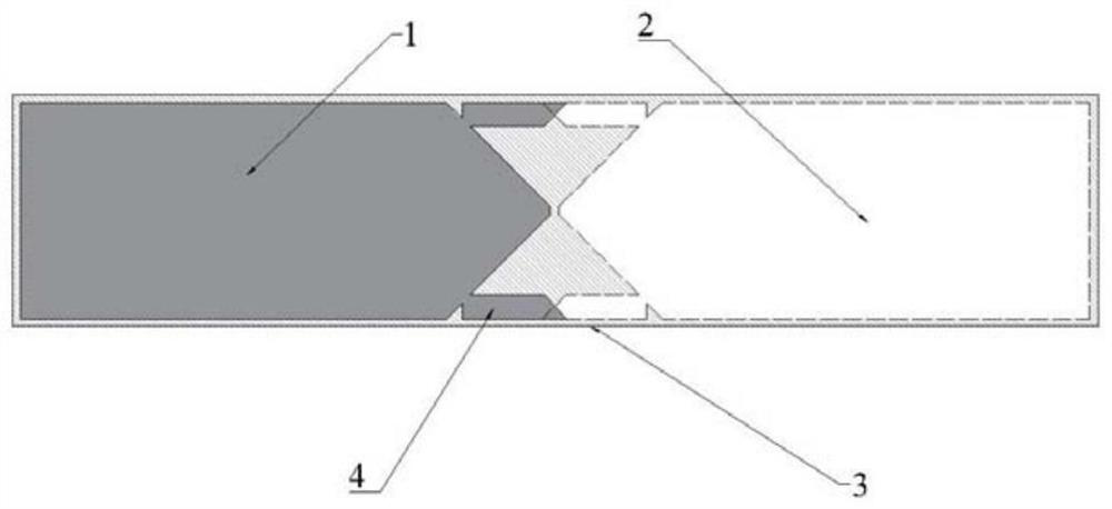
[0028] refer to Figure 1-4 , a broadband directional dipole antenna for ground penetrating radar, comprising a dipole antenna body and a semi-enclosed absorbing structure;

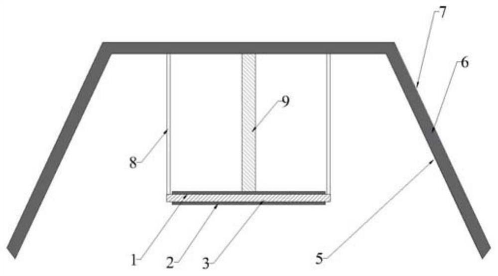
[0029] The absorbing structure has an opening side, and the dipole antenna body is arranged in the absorbing structure and located on the opening side, and the dipole antenna body is connected to the absorbing structure through a coaxial feeder 9 .

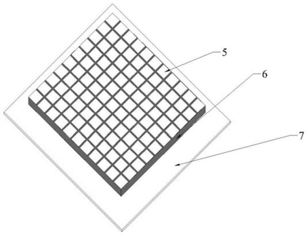
[0030] refer to figure 2 , the absorbing structure includes a micro-structure metal unit, a wave-absorbing layer, and a launch plate 7 from the inside to the outside. The cloth is formed, and the micro metal block is laid on the surface of the wave-absorbing layer 6, and the wave-absorbing layer 6 is bonded on the emitting plate 7.

[0031] Several micro-metal block...


PUM


Abstract

The invention discloses a broadband directional dipole antenna for a ground penetrating radar. The broadband directional dipole antenna comprises a dipole antenna body and a semi-enclosed wave-absorbing structure, the wave-absorbing structure is provided with an opening side, the dipole antenna body is arranged in the wave-absorbing structure and located on the opening side, and the dipole antenna body is connected with the wave-absorbing structure through a coaxial feeder line; and the wave-absorbing structure sequentially comprises a microstructure metal unit, a wave-absorbing layer and a transmitting plate from inside to outside, the frequency selection surface of the microstructure metal unit is located on the side close to the dipole antenna body, a micro metal block is laid on the surface of the wave-absorbing layer, and the wave-absorbing layer is bonded to the transmitting plate. The broadband directional dipole antenna is compact in structure, the overall thickness is not larger than 130 mm, the width is not larger than 350 mm, and the length is not larger than 900 m. The broadband directional dipole antenna can be used for an earth surface ground penetrating radar system and can also be used for an airborne ground penetrating radar system.

Description

technical field [0001] The invention relates to the design field of ground penetrating radar, in particular to a broadband directional dipole antenna for ground penetrating radar. Background technique [0002] Ground-penetrating radar is a geophysical method that uses high-frequency electromagnetic waves with a frequency between 25MHz and 4000MHz to reasonably evaluate and speculate the geometric structure, spatial location, and burial depth of underground media. GPR is economical, environmentally friendly, efficient and non-destructive, and can achieve high-resolution imaging. Therefore, it is widely used in engineering inspection, environmental protection, cultural relics and archaeology, disaster rescue, resource detection, hydrology and water conservancy and other fields. The ground penetrating radar works on the surface and needs to transmit detection signals underground. If an omnidirectional antenna is used, not only the energy of the signal transmitted underground is...

Claims


Application Information

Patent Timeline
Patent Type & Authority Applications(China)
IPC IPC(8): H01Q15/00H01Q17/00H01Q15/14H01Q1/38H01Q1/50G01V3/12
CPCH01Q15/0013H01Q17/004H01Q15/14H01Q1/38H01Q1/50G01V3/12
Inventor 嵇成高柴细元郭成李卫强赵丽群李国英刘先平窦如胜郭佶玙张艳龙张崇军
Owner BC P INC CHINA NAT PETROLEUM CORP
Why Eureka
Try Eureka