
A Ring Oscillator Frequency Modulation Circuit

A ring oscillator and frequency modulation technology, applied in power oscillators, automatic power control, electrical components, etc., can solve the problems of inability to match the voltage source, the traditional solution consumes a lot of power, and the integration area is large, and achieves low power consumption. , Small integration area, accurate frequency modulation effect

Active Publication Date: 2022-05-10
GUANGZHOU UNIVERSITY
View PDF7 Cites 0 Cited by
  • Summary
  • Abstract
  • Description
  • Claims
  • Application Information

AI Technical Summary

Problems solved by technology

[0003] The frequency modulation of the traditional MPPT circuit needs to know exactly the energy source and internal resistance, and the internal resistance of the energy source is greatly affected by the environment, so it cannot match the flexible and diverse voltage sources in practical applications, and the traditional scheme has the disadvantages of large power consumption and large integration area.

Method used


Image

  • A Ring Oscillator Frequency Modulation Circuit
  • A Ring Oscillator Frequency Modulation Circuit
  • A Ring Oscillator Frequency Modulation Circuit

Examples


Embodiment Construction

[0041] Embodiments of the present invention are described in detail below, examples of which are shown in the drawings, wherein the same or similar reference numerals designate the same or similar elements or elements having the same or similar functions throughout. The embodiments described below by referring to the figures are exemplary only for explaining the present invention and should not be construed as limiting the present invention.

[0042] In the description of the present invention, it should be understood that the orientation descriptions, such as up, down, front, back, left, right, etc. indicated orientations or positional relationships are based on the orientations or positional relationships shown in the drawings, and are only In order to facilitate the description of the present invention and simplify the description, it does not indicate or imply that the device or element referred to must have a specific orientation, be constructed and operated in a specific ...


PUM


Abstract

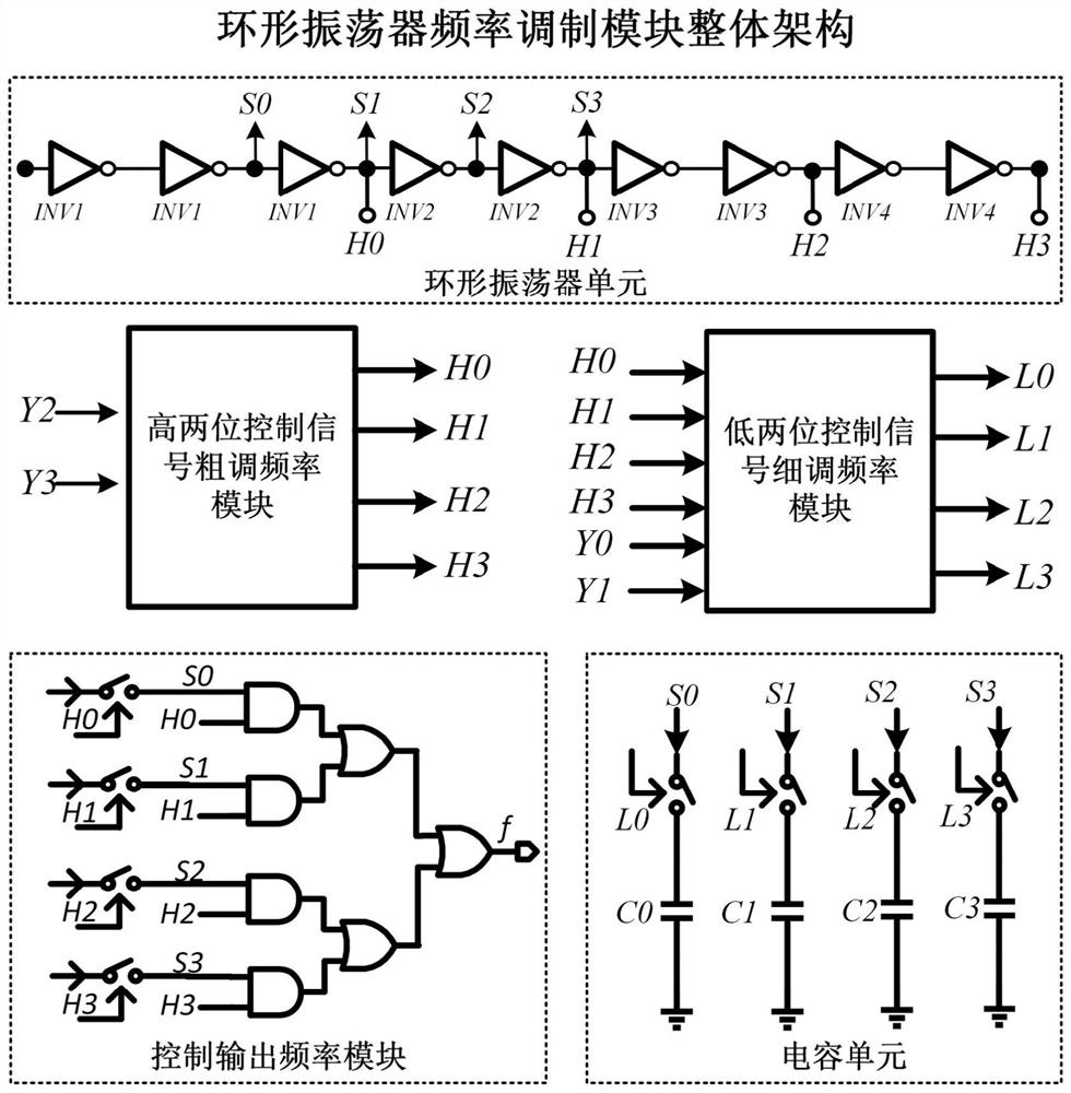
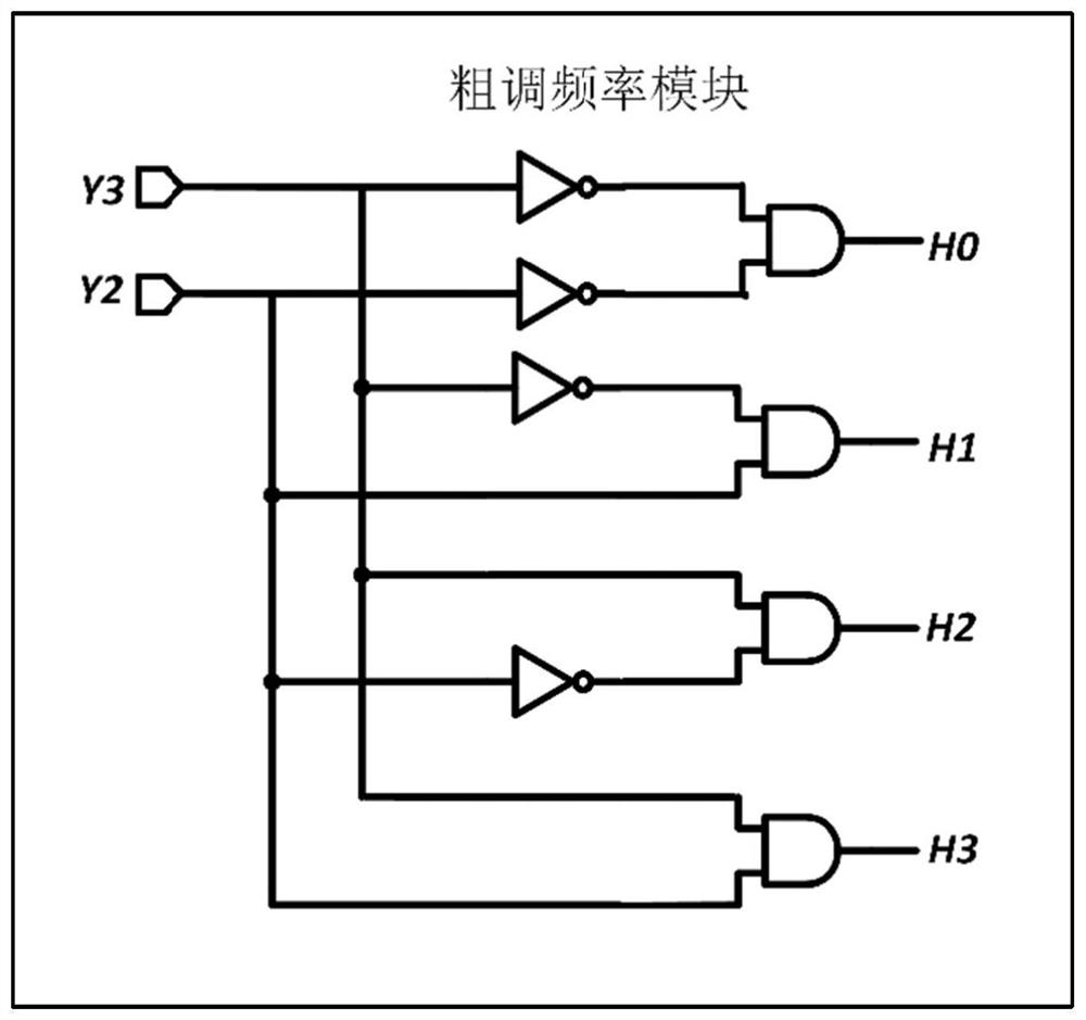
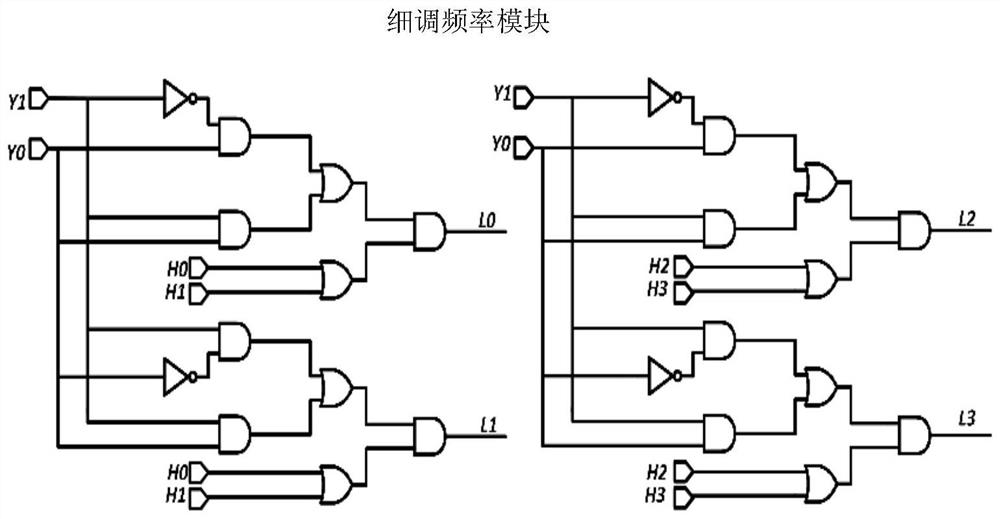
The invention discloses a ring oscillator frequency modulation circuit, comprising: a coarse frequency adjustment module, used for receiving the first counting signal and the second counting signal output by the counter in the maximum power point tracking circuit, and outputting the corresponding coarse adjustment frequency signal; the fine-tuning frequency module is used to receive the third counting signal and the fourth counting signal output by the counter in the maximum power point tracking circuit, and output the corresponding fine-tuning frequency signal; the ring oscillator frequency generation module is used to receive the coarse The frequency modulation signal and the fine adjustment frequency signal are used to generate a corresponding oscillation frequency, and the oscillation frequency is input to the maximum power point tracking circuit for frequency modulation. The invention can generate a stable oscillation frequency corresponding to the counting signal, so as to track the maximum power point; the invention has the advantages of small integration area, low power consumption, accurate frequency modulation and high stability. The present invention can be widely used in the field of integrated circuits.

Description

technical field [0001] The invention relates to the field of integrated circuits, in particular to a ring oscillator frequency modulation circuit. Background technique [0002] With the continuous development of energy harvesting technology, the collection and utilization of micro-power energy has begun to come into people's field of vision in recent years. This technology converts energy collected from the environment wasted in the form of light, heat, and vibration into electrical energy through an energy converter and stores it to provide energy for wireless sensor nodes. Therefore, a maximum power point tracking circuit is required in circuit design to maximize energy output power. Under this demand, a frequency modulation scheme for the maximum power point tracking circuit (MPPT) was proposed. Frequency modulation is a modulation mode used for maximum power point tracking in thermoelectric energy harvesting circuits. The equivalent input impedance of the resistor and ...

Claims


Application Information

Patent Timeline
Patent Type & Authority Patents(China)
IPC IPC(8): H03B5/04H03L7/099
CPCH03B5/04H03L7/099
Inventor 曾衍瀚林奕涵吴添贤杨敬慈陈伟坚李志贤陈美玲
Owner GUANGZHOU UNIVERSITY
Learn More