Transconductance Operational Amplifier Circuit and Cellular Neural Network

A transconductance operational amplifier and circuit technology, applied in the field of transconductance operational amplifier circuits and cellular neural networks, can solve the problems of high power consumption, complex structure, and large overall circuit integration area, so as to reduce power consumption, improve computing power, The effect of saving computing time

Inactive Publication Date: 2018-03-20
PEKING UNIV SHENZHEN GRADUATE SCHOOL +1
View PDF4 Cites 0 Cited by
  • Summary
  • Abstract
  • Description
  • Claims
  • Application Information

AI Technical Summary

Problems solved by technology

[0004] Therefore, the existing cellular neural network circuit structure is complex, the integration area of ​​the overall circuit is large, and the power consumption is relatively high.

Method used


Image

  • Transconductance Operational Amplifier Circuit and Cellular Neural Network
  • Transconductance Operational Amplifier Circuit and Cellular Neural Network
  • Transconductance Operational Amplifier Circuit and Cellular Neural Network

Examples


Embodiment 1

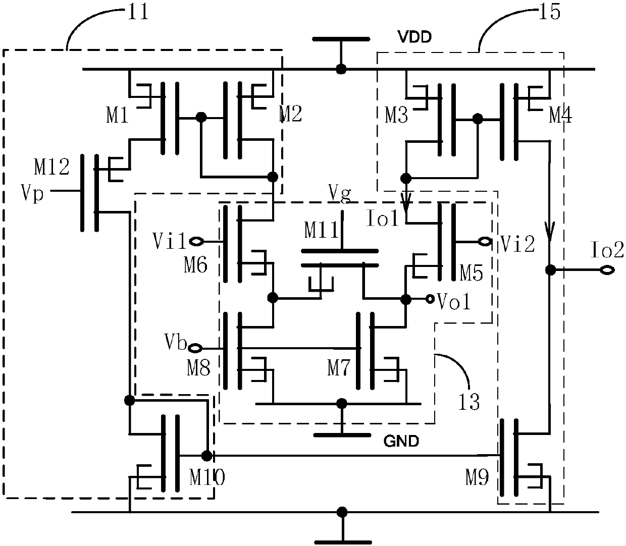
[0045] Please refer to figure 1 , the present application provides a transconductance operational amplifier circuit, which includes a ground terminal, a power supply voltage terminal, a current bias module 11 , a processing module 13 and a mirror module 15 . Wherein, the power supply voltage terminal is used to input the power supply voltage VDD. The current bias module 11 , the processing module 13 and the mirror module 15 are composed of tunneling field effect transistors.

[0046]The current bias module 11 is connected to the power supply voltage terminal and the ground terminal, and is connected to the processing module 13 at a first internal node for providing a bias current to the processing module 13 . In a preferred embodiment, the current bias module 11 includes a tunneling field effect transistor M1 , a tunneling field effect transistor M2 , a tunneling field effect transistor M12 and a tunneling field effect transistor M10 . Wherein, the gate of the tunneling fiel...

Embodiment 2

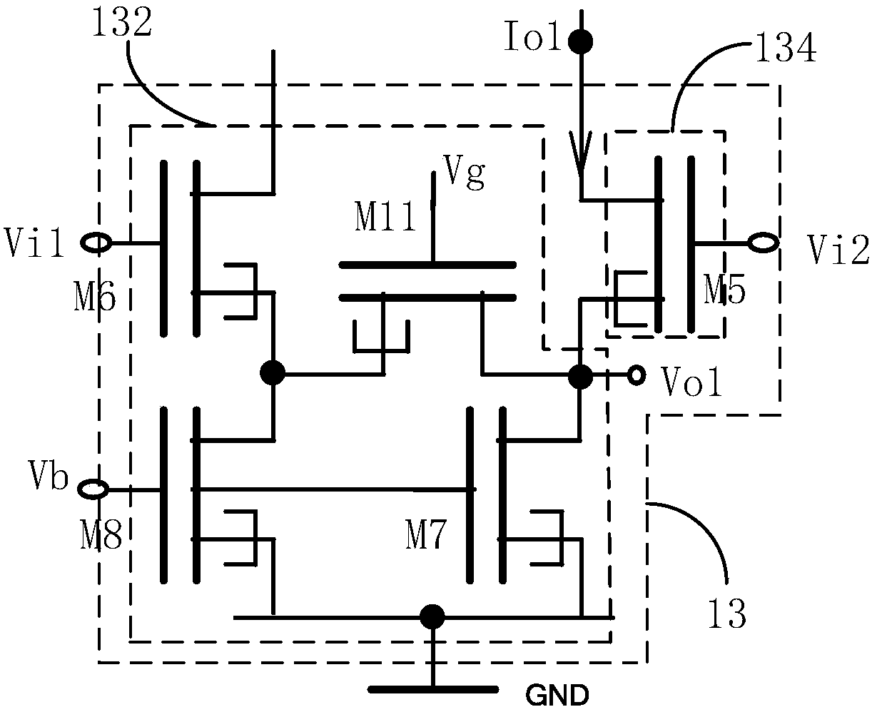
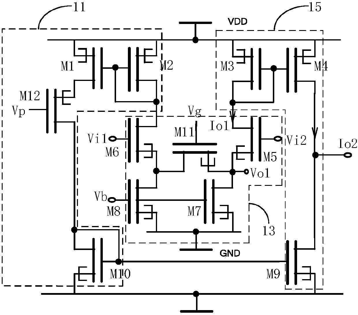
[0057] Please refer to image 3 , in another embodiment, the transconductance operational amplifier circuit of the present application is used to find the pixel with the minimum intensity. Wherein, the tunneling field effect transistor M11 is N-type, its drain is connected to the source of the tunneling field effect transistor M6 and the drain of the tunneling field effect transistor M8, and its source is connected to the source of the tunneling field effect transistor M5 and the drain of the tunneling field effect transistor M8. The drain of the tunneling field effect transistor M7.

[0058] Specifically, the magnitude of the voltage Vi2 represents the intensity of the pixel. By adjusting the fixed voltage Vi1, make and Vi1>Vi2. At this time, the N-type TFET tube M11 is turned on, and the transconductance operational amplifier circuit works normally. The higher the pixel intensity is, the higher the voltage of Vi2 is, and the voltage pull-down module 132 pulls down the sou...


PUM


Abstract

The application discloses a transconductance operation amplification circuit which comprises a ground connection end, a power source voltage end, a processing module, a current bias module and a mirror image module. The processing module comprises a first input end, a second input end and a current output end. The first input end is used for inputting adjustable fixed voltage Vi1, the second input end is used for inputting voltage Vi2, the current output end is used for outputting an amplified current Io1, and the processing module is used for determining the current Io1 according to difference between the fixed voltage Vi1 and the voltage Vi2. The current bias module is used for providing a bias current for the processing module, and the mirror image module is used for outputting an image current Io2 according to the current Io1; each of the current bias module, the processing module and the mirror image module consists of tunneling field effect transistors. The application also discloses a cell nerve network which comprises the transconductance operation amplification circuit. The transconductance operation amplification circuit and the cell nerve network in the application can help reduce whole circuit integration area and lower power consumption.

Description

technical field [0001] The application relates to the field of integrated circuits and cellular neural networks, in particular to a transconductance operational amplifier circuit and cellular neural networks. Background technique [0002] Cellular Neural Network (CNN) was proposed by Chua and Yang in 1988. Its basic circuit unit is called a cell, which is composed of linear and nonlinear circuit elements. Typical components are linear capacitors, linear resistors, linear and nonlinear controlled power supplies, and independent power supplies. A cellular neural network with a scale of M×N has a total of M×N cells arranged in M ​​rows and N columns. Cellular neural network is a kind of non-linear signal analog processor with local interconnection and double-valued output. These superior properties make cellular neural networks widely used in image processing, pattern recognition, biomedicine, automatic control, and secure communication. [0003] The theoretical design and ...

Claims


Application Information

Patent Timeline
Patent Type & Authority Patents(China)
IPC IPC(8): G06N3/063
CPCG06N3/063
Inventor 黄继攀黄宇谦王新安马芝赵秋奇鲁海芳杨志强高方林楚君陈红英
Owner PEKING UNIV SHENZHEN GRADUATE SCHOOL
Why Eureka
Try Eureka