High speed parallel-serial data switching system

A technology for converting systems and serial data, which is applied to parts of TV systems, TVs, color TVs, etc., can solve the problems of large area required for integration, poor implementability, large power consumption and noise, etc., to achieve Effects of area reduction required for integration, cost control, and power consumption reduction

Active Publication Date: 2009-09-30
深圳市力合微电子股份有限公司
View PDF1 Cites 0 Cited by
  • Summary
  • Abstract
  • Description
  • Claims
  • Application Information

AI Technical Summary

Problems solved by technology

[0006] 1. The frequency of 1.1.65G is too high, and it is difficult to design and implement with a general line width (such as 0.35um)
[0007] 2. The power consumption and noise generated by the high-speed phase-locked loop with a ten-fold frequency are relatively large, and the area required for integration is large and the cost is relatively high
[0008] Therefore, the prior art has high cost and poor implementability

Method used


Image

  • High speed parallel-serial data switching system
  • High speed parallel-serial data switching system
  • High speed parallel-serial data switching system

Examples


Embodiment Construction

[0028] The following describes the present invention in further detail based on the drawings and embodiments:

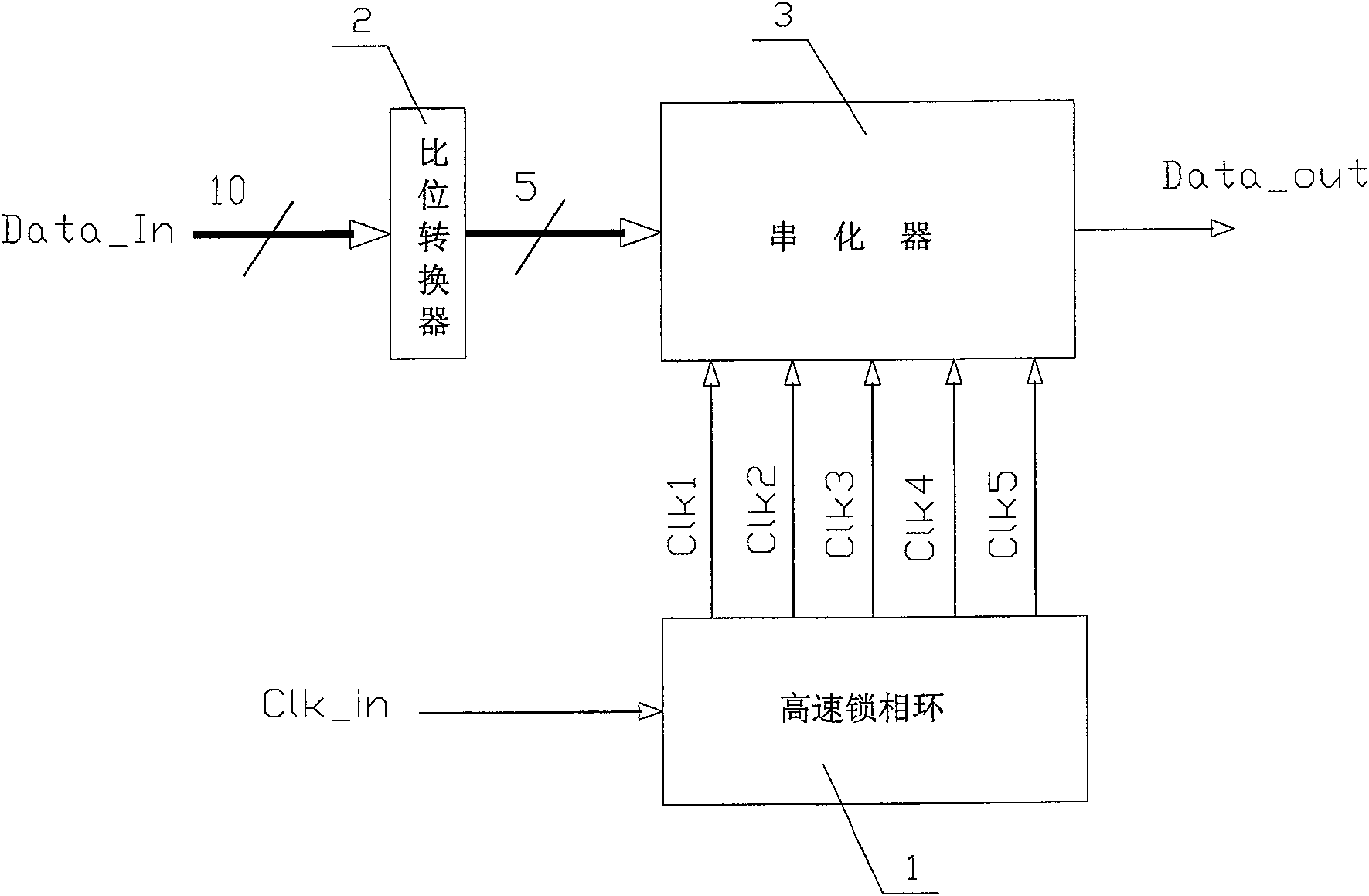
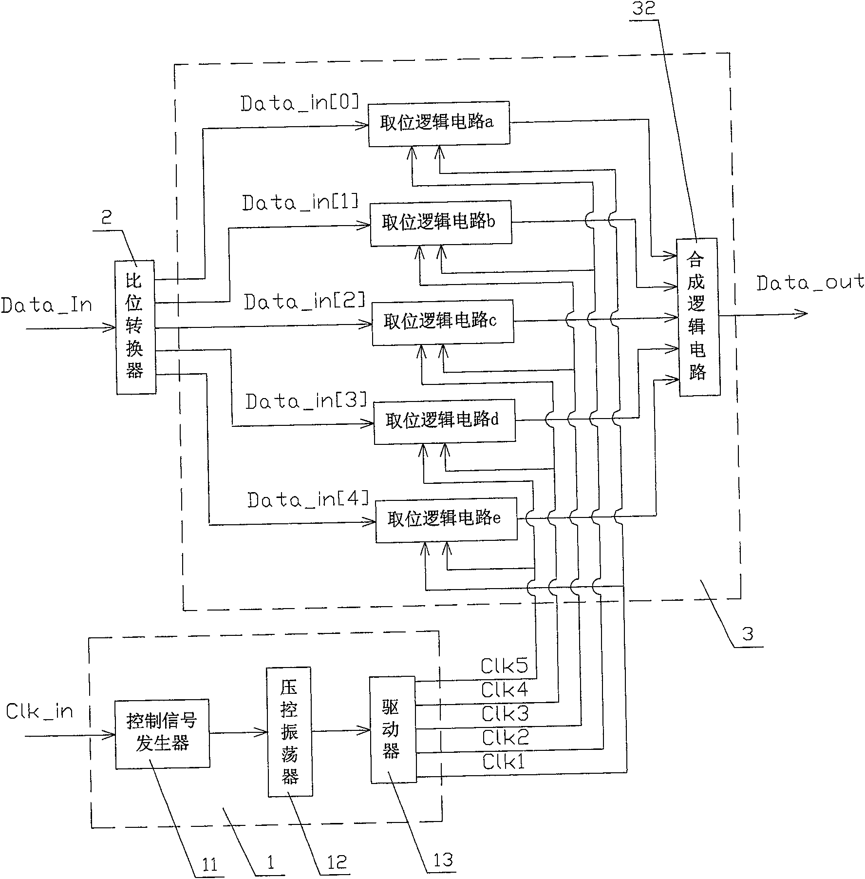
[0029] according to figure 2 with image 3 , The present invention includes a high-speed phase-locked loop 1, a bit-bit converter 2 and a serializer 3. The bit-bit converter 2 processes the input high-bit parallel data signal with a frequency multiplier clock to generate a low-bit parallel data output signal, Such as figure 1 As shown, the bit converter 2 multiplies the input 10-bit parallel data signal Data_In to generate a 5-bit parallel data signal Data_in[4:0], and the serializer 3 receives the parallel output signal from the bit converter 2. For the data signal Data_in[4:0], the serializer 3 generates a serial output data signal according to the clock signal generated by the high-speed phase-locked loop 1.

[0030] Such as image 3 with Figure 4 As shown, the high-speed phase-locked loop 1 includes a control signal generator 11, a voltage-controlled oscillator 12...


PUM


Abstract

A high-speed parallel-to-serial data conversion system involving electrical digital data processing, including a high-speed phase-locked loop, and also includes a ratio converter and a serializer, wherein the ratio converter uses a frequency multiplication clock for the input high-digit parallel data signal Perform processing to generate low-digit parallel data output signals: the serializer receives the parallel data signals output by the bit converter, and the serializer generates serial output data signals according to the clock signal generated by the high-speed phase-locked loop; the high-speed lock The phase loop includes a control signal generator and a voltage-controlled oscillator. The control signal generator generates phase / frequency difference signals according to different clock input signals to obtain related current control signals. The voltage-controlled oscillator generates N same frequency signals according to the current control signals. For clocks with different phases, the phase difference between two adjacent clocks is 360 / N°, and the phase difference between the Nth clock and the first clock is also 360 / N°. The invention has low cost and strong implementability.

Description

Technical field [0001] The present invention relates to electrical digital data processing, in particular to a high-speed parallel-serial data conversion system. Background technique [0002] Digital Visual Interface (DVI: Digital Visual Interface) is a standard for connecting source systems and display devices, especially pure digital display devices, such as liquid crystal displays. Such as figure 1 As shown, a DVI display system includes a transmitter and a receiver. The transmitter receives parallel signals from the image signal processor. These signals include a data signal Data, a clock signal Clk, a data enable signal DE, and a horizontal synchronization control signal. HSYNC, vertical synchronization control signal VSYNC, the transmitter can be built into the graphics card chip, or it can appear on the graphics card printed circuit board PCB in the form of an additional chip; the receiver receives the serial digital signal, decodes it and transmits it to the digital disp...

Claims


Application Information

Patent Timeline
Patent Type & Authority Patents(China)
IPC IPC(8): H04N5/765
Inventor 刘元成周晓新刘鲲
Owner 深圳市力合微电子股份有限公司
Why Eureka
Try Eureka