Microfluidic paper chip, preparation method thereof, microfluidic paper chip detection system and application

A microfluidic paper chip, paper chip technology, applied in fluid controllers, chemical instruments and methods, measurement devices, etc., can solve problems such as non-specific adsorption, contamination of samples, loss, etc.

Active Publication Date: 2021-06-08
HUNAN NORMAL UNIVERSITY
View PDF11 Cites 3 Cited by
  • Summary
  • Abstract
  • Description
  • Claims
  • Application Information

AI Technical Summary

Problems solved by technology

However, in the process of stacking or folding, precise alignment and tight fit between layers are required, which is cumbersome to operate, and the fluid is easily lost due to insufficient tight fit between layers during the layer-by-layer flow, and in the stacking process Need to use double-sided tape, it is easy to produce non-specific adsorption during the analysis and determination process, pollute the sample, and have a certain impact on the accuracy of the analysis results

Method used


Image

  • Microfluidic paper chip, preparation method thereof, microfluidic paper chip detection system and application
  • Microfluidic paper chip, preparation method thereof, microfluidic paper chip detection system and application
  • Microfluidic paper chip, preparation method thereof, microfluidic paper chip detection system and application

Examples


Embodiment 1

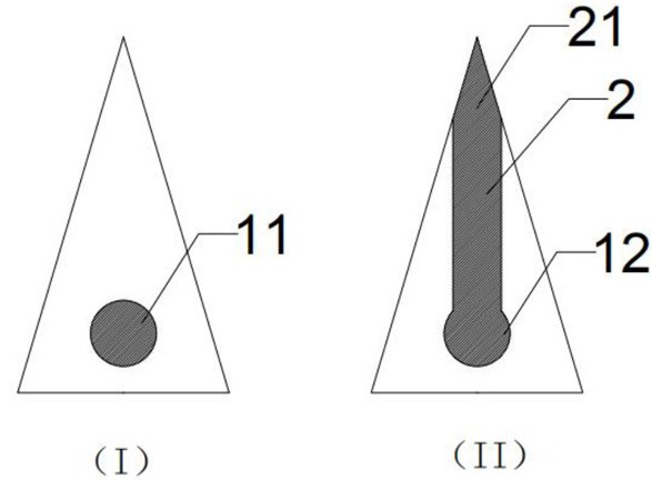
[0073] A microfluidic paper chip, such as figure 1As shown, (I) is the front view of the microfluidic paper chip, (II) is the back view of the microfluidic paper chip; The back view of the paper chip includes a detection area 2 , a filtrate area 12 and a sampling port 21 in the detection area. The sample injection area 11, the filtrate area 12 and the detection area 2 of the microfluidic paper chip are all located in the hydrophilic area, and the other non-shaded areas are hydrophobic areas. The sample injection area 11 and the filtrate area 12 of the microfluidic paper chip are located at corresponding positions on both sides of the microfluidic paper chip. The sample injection area 11 is located at one end of the microfluidic paper chip, and the detection area 2 is strip-shaped and connected to the filtrate area 12 . The sampling area 11 of the microfluidic paper chip is covered with a sulfonic acid-based resin.

Embodiment 2

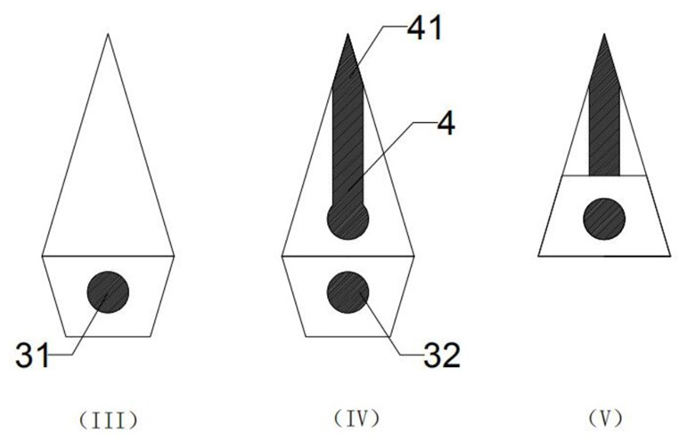
[0075] A microfluidic paper chip, such as figure 2 As shown, (III) is the front view of the microfluidic paper chip, (IV) is the back view of the microfluidic paper chip, (V) is the schematic diagram of the folded microfluidic paper chip, and the front view of the microfluidic paper chip The figure includes the sampling area 31, and the back view of the microfluidic paper chip includes the detection area 4, the filtrate area 32 and the detection area sampling port 41, and the sampling area, the detection area and the filtrate area are all located on the hydrophilic surface of the microfluidic paper chip. area, and other non-shaded areas are hydrophobic areas. The sample injection area 31 and the filtrate area 32 of the microfluidic paper chip are located at corresponding positions on both sides of the microfluidic paper chip. The position of the filtrate area 32 is separated from the detection area 4 before folding. After folding, the filtrate area 32 covers the part of the ...

Embodiment 3

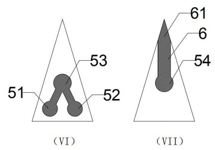
[0077] A microfluidic paper chip, such as image 3 As shown, (VI) is the front view of the microfluidic paper chip, and (VII) is the back view of the microfluidic paper chip. Sample zone reaction zone 53 and the first sampling zone sampling point 51, the second sampling zone sampling point 52, the first sampling zone sampling point 51 and the second sampling zone sampling point 52 pass through the hydrophilic zone channel Connected to the reaction zone 53 of the sample introduction area; the sample introduction area is covered with sulfonic acid-based resin. The back view of the microfluidic paper chip includes a detection area 6, a filtrate area 54, and a sampling port 61 in the detection area. The sampling area, the filtrate area, and the detection area of ​​the microfluidic paper chip are all located in the hydrophilic area on the paper base. The other unshaded regions of the base are hydrophobic regions. The sample injection area reaction area 53 and the filtrate area 54...


PUM


Abstract

The invention provides a microfluidic paper chip, which comprises a sample introduction area and a detection area, wherein the sample introduction area and the detection area are hydrophilic areas, and the periphery of the sample introduction area and the detection area is a hydrophobic area; the sample introduction area is positioned on one side of the paper chip, and the detection area is positioned on the other side; and the sample introduction area can penetrate through the paper base to penetrate through the other side of the paper chip to form a filtrate area, and the filtrate area enables filtrate to flow to the detection area in a contact mode or a non-contact mode. The invention further discloses a method for preparing the microfluidic paper chip and a detection system based on the microfluidic paper chip, and the system is applied to detection of components of food, vegetables, traditional Chinese medicinal materials and blood samples. The paper chip disclosed by the invention is simple and convenient to use, low in cost and more suitable for detecting substances with relatively small sample quantity. When a sample injection solution is ionized and sprayed, a signal entering a mass spectrometer is stronger, and the detection precision is higher. During detection operation, pollution can be prevented, the accuracy of detection data is ensured, and the mass spectrometer is prevented from being damaged.

Description

technical field [0001] The invention relates to a microfluidic paper chip, a preparation method thereof, a detection system and application of the microfluidic paper chip, and belongs to the technical field of chemical composition testing. Background technique [0002] The microfluidic paper chip is to establish a "hydrophobic barrier" and "hydrophilic channel" in a specific area of ​​the filter paper, and then construct a paper-based microfluidic chip with a certain network structure of hydrophilic and hydrophobic channels. The microfluidic paper chip was proposed by the team of Professor Whitesides of Harvard University in the United States in 2007, and has become a promising development direction in microfluidic chips. Compared with traditional microfluidic chips based on silicon, glass and plastic, microfluidic paper chips have many advantages such as wide source of raw materials, low price, easy processing, good compatibility with biological samples, and degradability. ...

Claims


Application Information

Patent Timeline
Patent Type & Authority Applications(China)
IPC IPC(8): B01L3/00G01N27/68
CPCB01L3/5027B01L3/502707B01L3/50273B01L3/502753B01L2200/0642B01L2200/10B01L2300/126B01L2300/161B01L2300/165B01L2400/0415G01N27/68
Inventor 马铭陈东盈陈波闵可郭萍
Owner HUNAN NORMAL UNIVERSITY
Why Eureka
Try Eureka