Chip capacitor packaging device

A chip capacitor and electrical connection technology, applied in packaging, transportation packaging, packaging protection, etc., can solve the problems of vacancies, filling vacancies, and inability to retreat in winding tapes

Inactive Publication Date: 2021-06-08
FUJICON ELECTRONICS TECH SHAOGUAN
View PDF5 Cites 2 Cited by
  • Summary
  • Abstract
  • Description
  • Claims
  • Application Information

AI Technical Summary

Problems solved by technology

However, because there is no suitable device, it is difficult to remove the chip capacitor from the processing turntable when it is unloaded, and the transportation after removal is easy to cause the chip capacitor to flip or overlap, and the finished product can only be piled up after removal, which is not easy Separate the chip capacitors one by one and align them with the card slots on the winding tape. If the operator intervenes, it will affect the packaging efficiency and effect
[0003] Moreover, when the unqualified chip capacitors are removed in the pre-steps, there will be vacancies in the rewinding tape that has been moving forward, and the subsequent rewinding can only move forward because the rewinding tape needs to be tightened, and cannot retreat to fill the gap. bit
In addition, if the rewinding belt is only driven by the tightening of the reel, the rewinding belt will always be in a tight state, and in the position without support, the rewinding belt is easy to break, which affects the packaging effect

Method used


Image

  • Chip capacitor packaging device
  • Chip capacitor packaging device
  • Chip capacitor packaging device

Examples


Embodiment Construction

[0032] The present invention will be described in detail below in conjunction with the accompanying drawings and embodiments.

[0033] It is worth noting that the orientation words such as "up" and "down" involved in this article are all determined relative to the perspective of the drawings, and are only for the convenience of description, and cannot be understood as limitations on the technical solution.

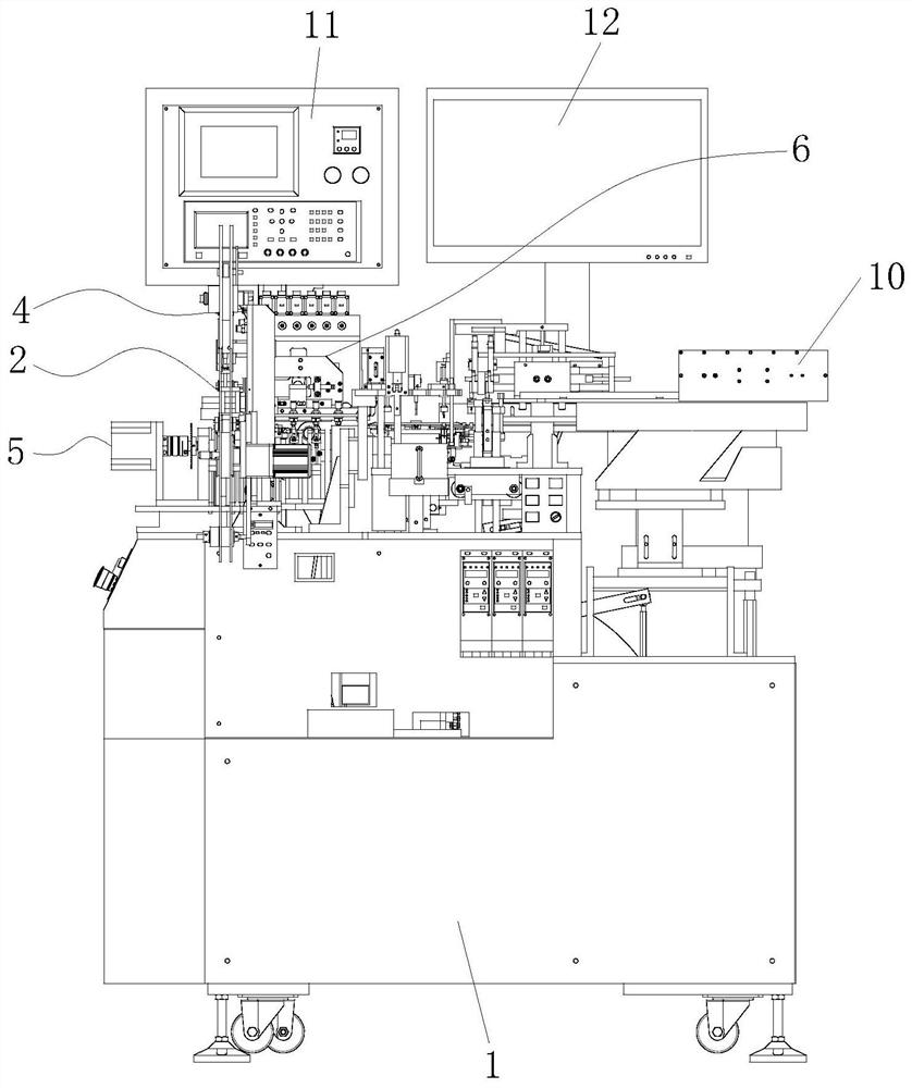
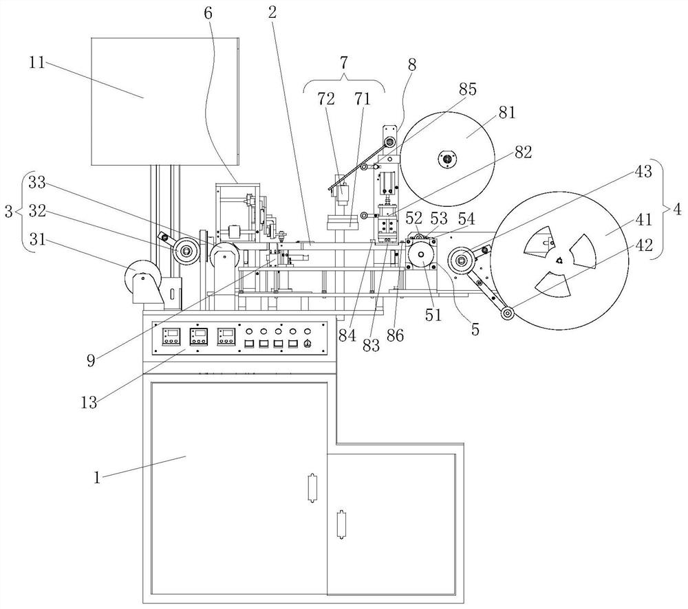
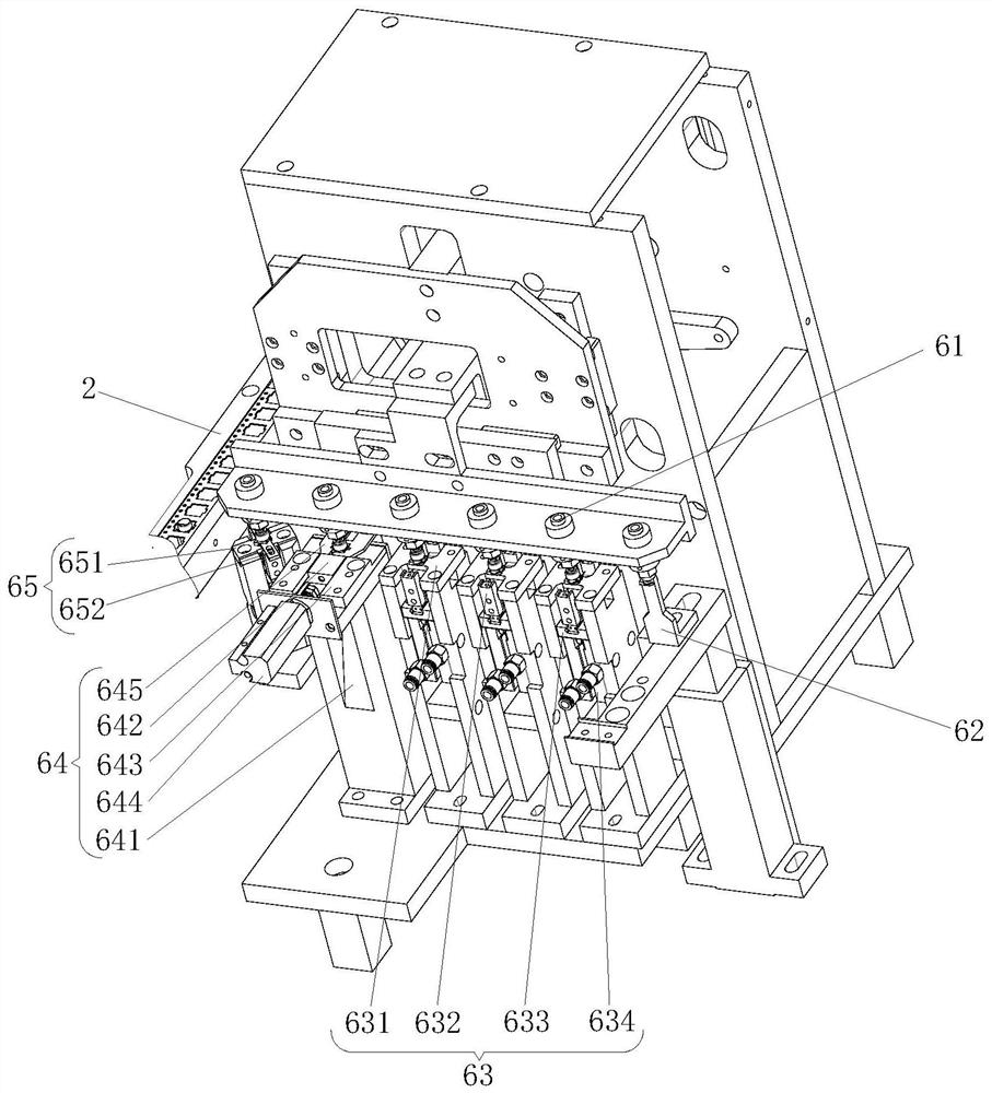
[0034] Such as Figure 1 ~ Figure 3As shown, a chip capacitor packaging device includes a console 1, a control system is provided in the console 1, and the control system is electrically connected to a leakage short circuit tester 11, a display screen 12 and an electric control switch 13, and the leakage short circuit tester 11 is arranged on the top of the console 1, and the existing leakage short-circuit tester 11 can be used to set it up, so as to detect and ensure that the product meets the quality requirements; 13 is located on one side of the console 1, the console ...


PUM


Abstract

The invention relates to a chip capacitor packaging device which comprises a control table. A belt passing bridge is erected on the control table; a belt supplying mechanism and a winding mechanism are arranged at the two ends of the belt passing bridge correspondingly; a transmission mechanism is used for driving a winding belt to step step by step and enter the winding mechanism for winding; a vacuum conveying mechanism, a shooting detection mechanism and an adhesive tape heat sealing mechanism are sequentially arranged on the belt passing bridge in the moving direction of the winding belt; and the vacuum conveying mechanism comprises a plurality of suction nozzles arranged in an arrayed mode, and the suction nozzles suck chip capacitors to be placed and moved on bases one by one, so that the chip capacitors are placed in the groove holes of the winding belt one by one. According to the chip capacitor packaging device, the belt passing bridge is used as a basis, the machined chip capacitors are conveyed from a rotating disc, all packaging procedures are completed in sequence, packaging of the chip capacitors one by one can be well completed, packaging is completed in combination with vacuum conveying, the one-by-one packaging efficiency and effect of the chip capacitors can be improved, and the automatic procedure of the series of steps can be completed.

Description

technical field [0001] The present invention relates to the technical field of chip capacitor production process, more specifically, it relates to a chip capacitor packaging device. Background technique [0002] Capacitors are one of the electronic components widely used in electronic equipment, and are widely used in DC blocking, coupling, bypass, filtering, tuning loops, energy conversion, control circuits, etc. After the chip capacitor is produced, due to its small size, it needs to be packed with a winding tape to facilitate storage and prevent loss. At present, due to the popularization of automated production, the cutting and packaging process of chip capacitors is usually completed by the assembly line, that is, a single finished capacitor is put into the card position of the winding tape and then plastic-packed. However, because there is no suitable device, it is difficult to remove the chip capacitor from the processing turntable when it is unloaded, and the transp...

Claims


Application Information

Patent Timeline
Patent Type & Authority Applications(China)
IPC IPC(8): B65B35/38B65B57/14B65B51/14B65B15/04
CPCB65B35/38B65B57/14B65B51/14B65B15/04
Inventor 杨海铃黄瑞剑杨云飞刘福生
Owner FUJICON ELECTRONICS TECH SHAOGUAN
Why Eureka
Try Eureka