High-water-level basement bottom plate lower-layer drainage zone rainwater recycling integrated circulation system structure and construction method thereof
A basement floor and circulation system technology, applied in waterway systems, infrastructure engineering, chemical instruments and methods, etc., can solve problems such as poor quality of basement waterproofing, increased difficulty in underground structure construction, and leakage of structural floor backwater, etc. Achieve the effects of less construction difficulty, faster construction progress, and saving construction water costs
- Summary
- Abstract
- Description
- Claims
- Application Information
AI Technical Summary
Problems solved by technology
Method used
Image

Examples
Embodiment Construction
[0032] The present invention will be further described in detail below in conjunction with the accompanying drawings and embodiments.
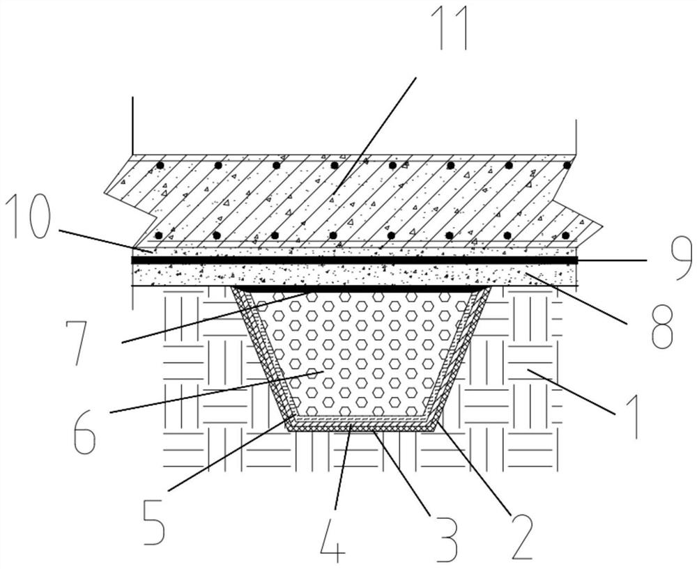
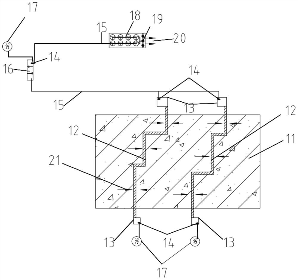
[0033] Such as figure 1 , 2 As shown, an integrated circulation system structure for rainwater reuse in the drainage zone under the floor of a high water level basement, the structure includes a drainage channel 1, a drainage belt 12, a storage tank 13, a tertiary sedimentation tank 16, and a water storage bucket 18.
[0034] The hydrophobic channel 1 is arranged under the bottom plate 11 of the basement.
[0035] A reservoir 13 is provided outside the retaining side wall of the basement.
[0036] A permanent automatic water pump 14 is set in the reservoir 13, and the automatic water pump 14 is connected to the tertiary sedimentation tank 16 through a DN100 galvanized pipe 15.
[0037] An automatic water pump 14 is arranged in the three-stage sedimentation tank 16, and the automatic water pump 14 is connected to a water storage bucket 18 th...
PUM
 Abstract
Description
Claims
Application Information