Exhaust system of vehicle

An exhaust system and vehicle technology, applied in the direction of exhaust treatment, exhaust device, electronic control of exhaust treatment device, etc.

Inactive Publication Date: 2021-06-08
ZHEJIANG GEELY HOLDING (GROUP) CO LTD +3
View PDF5 Cites 3 Cited by
  • Summary
  • Abstract
  • Description
  • Claims
  • Application Information

AI Technical Summary

Problems solved by technology

[0005] The present invention aims at the above-mentioned problems existing in the prior art, and provides an exhaust system of a vehicle. The technical problem to be solved by the present invention is: how to reduce the pollution emission when the vehicle is cold started

Method used


Image

  • Exhaust system of vehicle

Examples


Embodiment 1

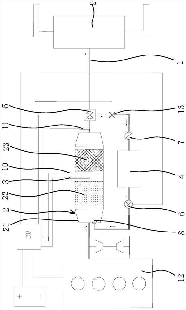
[0027] like figure 1 As shown, this embodiment includes an exhaust pipe 1, a gas storage element 4, an electric control 5, and a catalytic converter 2 arranged on the exhaust pipe 1 and connected between the inlet and the outlet of the exhaust pipe 1, and the inlet of the exhaust pipe 1 Used to communicate with the outlet of the engine 12 , and the outlet of the exhaust pipe 1 is used to communicate with the muffler 9 . The catalytic converter 2 is provided with a temperature sensor 3 for detecting the gas temperature. The gas storage part 4 is a gas storage tank or a gas storage box, and the inlet and outlet of the gas storage part 4 communicate with the outlet and the inlet of the catalytic converter 2 respectively through pipes. The electric control 5 is located at the intersection of the pipe between the outlet of the catalytic converter 2 and the inlet of the gas storage part 4 and the exhaust pipe 1. The electric control 5 is a three-way solenoid valve with an inlet, an...

Embodiment 2

[0034] The technical solution of this embodiment is basically the same as the technical solution of Embodiment 1, the difference being that the electric control 5 in this embodiment includes solenoid valve 1 and solenoid valve 2 both having an inlet and an outlet, and solenoid valve 1 is set On the exhaust pipe 1 and between the outlet of the catalytic converter 2 and the outlet of the exhaust pipe 1 , the solenoid valve 2 is arranged on the pipeline between the outlet of the catalytic converter 2 and the inlet of the gas storage element 4 . The pipeline between the outlet of electromagnetic valve two and the inlet of air storage part 4 is provided with air pump one 13 and check valve 7, and the inlet of air pump one 13 is communicated with the outlet of electromagnetic valve two, and the outlet of air pump one 13 is connected with check valve. The inlet of 7 communicates, and the outlet of one-way valve 7 communicates with the inlet of gas storage element 4 .

[0035] The ele...

Embodiment 3

[0037] The technical solution of the present embodiment is basically the same as that of the first embodiment, the difference is that the present embodiment is not provided with an air pump two on the pipeline between the outlet of the gas storage part 4 and the inlet of the catalytic converter 2, but on the A pressure sensor 3 is arranged inside the gas storage part 4 to ensure that the exhaust gas in the gas storage part 4 flows to the catalytic converter 2 when the electric control valve 6 is opened. When the temperature sensor 3 detects that the gas temperature in the catalytic converter 2 is below the set value, the ECU controls the electric control 5 to connect the outlet of the catalytic converter 2 with the inlet of the gas storage part 4 and disconnect the outlet of the catalytic converter 2 and the outlet of the exhaust pipe 1, and at the same time Control air pump one 13 to open and electric control valve 6 to close, so that the exhaust gas pretreated by catalytic co...


PUM


Abstract

The invention provides an exhaust system of a vehicle, and belongs to the technical field of automobiles. The technical problem that the pollution emission is high when cold starting of an existing engine is conducted is solved by the exhaust system. The exhaust system of the vehicle comprises an exhaust pipe and a catalytic converter, wherein a temperature sensor which is used for detecting the temperature of gas is arranged in the catalytic converter. The exhaust system further comprises a gas storage part and an electric control part, wherein an inlet and an outlet of the gas storage part correspondingly communicate with an outlet and an inlet of the catalytic converter through pipelines. When the temperature sensor detects that the temperature is smaller than a set value, the electric control part can communicate with the outlet of the catalytic converter and the inlet of the gas storage part and disconnect the outlet of the catalytic converter and an outlet of the exhaust pipe at the same time; and when the temperature sensor detects that the temperature is larger than or equal to the set value, the electric control part can disconnect the outlet of the catalytic converter and the inlet of the gas storage part and communicate with the outlet of the catalytic converter and the outlet of the exhaust pipe at the same time. According to the exhaust system of the vehicle, the pollutant emission in the cold starting process of the vehicle is remarkably reduced.

Description

technical field [0001] The invention belongs to the technical field of automobiles, and in particular relates to an exhaust system of a vehicle. Background technique [0002] The emission reduction of automobile exhaust pollutants usually adopts catalytic treatment technology. With the development of the automobile industry and the early implementation of the National VI emission standard, the catalytic conversion efficiency of existing catalytic converters is already very high. At present, the main pollution of automobile exhaust comes from the cold start stage of the engine. During the cold start, the temperature of the exhaust gas discharged from the exhaust port of the engine is too low to reach the ignition temperature of the catalytic converter (about 300 ℃, and the catalytic converter can only be ignited after 30 seconds after a cold start. ), leading to low catalytic conversion efficiency and high pollution emissions. [0003] In order to solve this problem, the exi...

Claims


Application Information

Patent Timeline
Patent Type & Authority Applications(China)
IPC IPC(8): F01N3/20F01N9/00F01N11/00
CPCF01N3/20F01N9/00F01N11/002Y02T10/40Y02A50/20
Inventor 杨建宁会娟李荣平李晓娟宋志辉王瑞平肖逸阁
Owner ZHEJIANG GEELY HOLDING (GROUP) CO LTD
Why Eureka
Try Eureka