Unmanned aerial vehicle bridge floor coverage motion planning method

A motion planning, bridge deck technology, applied in non-electric variable control, instruments, control/regulation systems, etc., can solve the problems of long-time sampling, large amount of calculation, and considering the flight stability of UAVs, etc. Achieve the effect of ensuring coverage resolution, improving flight stability, and easy trajectory execution

Pending Publication Date: 2021-06-08
HARBIN INST OF TECH
View PDF1 Cites 2 Cited by
  • Summary
  • Abstract
  • Description
  • Claims
  • Application Information

AI Technical Summary

Problems solved by technology

The disadvantage of this algorithm is that it may take a long time to sample to ensure that a feasible trajectory is found, which reduces the real-time performance of the algorithm, and at the same time, the amount of calculation is too large
However, the current research direction has hardly conducted in-depth research on the motion planning problem of UAVs in this scenario.
For coverage motion planning, the current research basically refers to path planning, and there is no relevant in-depth research on how to give the motion trajectory of time parameters according to the path
And in the coverage process, the flight stability of the UAV is not taken into consideration, which is not suitable for road and bridge inspection tasks that require high imaging quality

Method used


Image

  • Unmanned aerial vehicle bridge floor coverage motion planning method
  • Unmanned aerial vehicle bridge floor coverage motion planning method
  • Unmanned aerial vehicle bridge floor coverage motion planning method

Examples


specific Embodiment approach 1

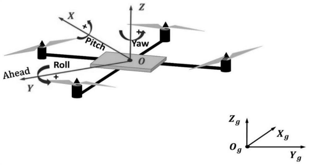
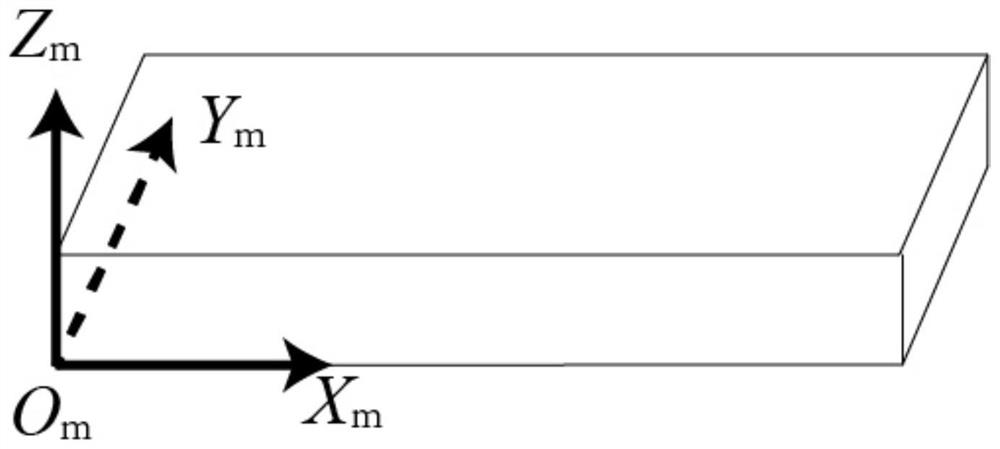
[0092] Specific implementation mode one: combine figure 1 , figure 2 and image 3 Describe this embodiment, a kind of unmanned aerial vehicle deck coverage motion planning method described in this embodiment is realized according to the following steps:

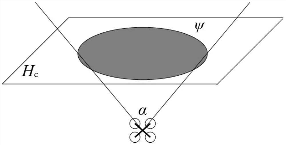
[0093] Step 1: Establish a geographic coordinate system, a body coordinate system, and a bridge deck coordinate system, and determine a sensor measurement model.

[0094] Establish the body coordinate system, the origin O of the body coordinate system OXYZ is taken as the center of mass of the quadrotor, the centerline of the two motors in the direction of the quadrotor head is taken as the longitudinal axis OY of the body, and the centerline of the two motors on the right side of the quadrotor is taken as the OX axis, OZ Satisfy the right-hand rule, that is, it is perpendicular to the plane of the body, and upward is the positive direction. Establish geographic coordinate system, geographic coordinate system O g x g Y ...

specific Embodiment approach 2

[0105] Specific embodiment two: the difference between this embodiment and specific embodiment one is: decomposing the bridge deck topology described in step two and adopting a bow-shaped covering path for each covering unit. The specific process is as follows:

[0106] Considering a rectangular bridge deck, the middle part becomes an obstacle on the 2D plane due to the connection of piers, such as Figure 4 shown. Let the length of the bridge deck be l b , then the straight line cluster {x m =x mi |x mi ∈[0,l b ]} Slice scan the bridge deck. When the number of segments of the straight line changes, record the point of the corresponding obstacle space and use it as the vertex. Such as Figure 4 As shown, at the vertex V 1 ,V 2When between, the segment number of the straight line inside the bridge deck is 1; at the vertex V 2 ,V 3 When between, the number of straight line segments inside the bridge deck is 2; at the vertex V 3 ,V 4 When between, the number of strai...

specific Embodiment approach 3

[0115] Specific implementation mode three: the difference between this implementation mode and specific implementation modes one to two is: the specific process of determining the unit coverage sequence described in step three is:

[0116] Let the vertex set of the bridge deck V={v 1 ,v 2 ,…}, the set of edges of the bridge deck E={E 1 ,E 2 ,...}. The connectivity matrix defining the edges and vertices of the bridge deck is A ne , A ne element a in ne Represents the connectivity of edges and vertices in an undirected graph, when a ne = 1, it means that the edge e∈E connects the vertex n∈V. On this basis, the following linear optimization problems can be constructed:

[0117]

[0118] The following conditions

[0119]

[0120]

[0121]

[0122] Among them, when the vertex n initially has an odd number of connections, b n =1, otherwise when there are even number of connections b n =0. w n is an integer variable, and b n Adjusting the equality constraint...


PUM


Abstract

The invention discloses an unmanned aerial vehicle bridge floor coverage motion planning method, belongs to the technical field of unmanned aerial vehicle control, and aims to solve the motion planning problem that an unmanned aerial vehicle stably completes the full coverage of the bridge floor and meets the coverage resolution requirement in an automatic detection task of a bridge surface. The method comprises the following steps of firstly, establishing a geographic coordinate system, an airframe coordinate system and a bridge floor coordinate system, giving a measurement model of an airborne camera, and giving the definitions of a coverage space, a coverage surface and the coverage resolution; secondly, decomposing a topological structure of the bridge floor by adopting a linear scanning form, and determining a bow-shaped coverage path for each decomposition unit; then determining the coverage sequence of the units by adopting an integer optimization method; then giving two mathematical descriptions of the flight space of the unmanned aerial vehicle under a coverage task by combining the distance range from the unmanned aerial vehicle to the bridge floor; and finally, taking the flight stability of the unmanned aerial vehicle as an index, and combining with limitations, such as position, speed, acceleration, flight space, full coverage requirements, etc., providing a method for obtaining a motion trail function by adopting curve optimization. The method is suitable for the unmanned aerial vehicle to quickly and stably complete the movement track planning of full coverage of the bridge floor under a bridge detection task.

Description

technical field [0001] The invention relates to a four-rotor unmanned aerial vehicle deck coverage motion planning method, which belongs to the technical field of unmanned aerial vehicle control. Background technique [0002] UAV is an unmanned aircraft that is controlled by radio remote control or autonomously by a program. It has the advantages of strong environmental adaptability, high maneuverability, relatively low cost, and the ability to perform long-term tasks autonomously. Therefore, it is widely used in military applications. , Civil fields, including environmental monitoring, agricultural plant maintenance, ground survey and assessment, emergency response, aerial photography and other fields. UAVs can be roughly divided into the following three categories according to the power used: fixed wing; rotary wing; flapping wing. Among all kinds of drones, multi-rotor drones, especially quadrotor drones, have the advantages of good maneuverability, better stability, lar...

Claims


Application Information

Patent Timeline
Patent Type & Authority Applications(China)
IPC IPC(8): G05D1/10
CPCG05D1/101
Inventor 郝宁李元红贺风华姚昊迪马杰
Owner HARBIN INST OF TECH
Why Eureka
Try Eureka