Flue gas filtering and purifying device for vacuum filter

A vacuum filter, filtration and purification technology, applied in the fields of dispersed particle filtration, transportation and packaging, chemical instruments and methods, etc., can solve the problems of poor flue gas filtration and purification effect, small volume, inability to work continuously, etc., to achieve effective Filter and purify, increase the contact area, and ensure the effect of purification effect

Active Publication Date: 2021-06-11
DATANG HUAIBEI POWER PLANT
View PDF17 Cites 1 Cited by
  • Summary
  • Abstract
  • Description
  • Claims
  • Application Information

AI Technical Summary

Problems solved by technology

[0002] Vacuum filter is a large-scale filtering equipment capable of continuous operation. It has the outstanding characteristics of large flow, high-precision filtration, and easy automatic control. Its filtering capacity can be used for a single machine or for a certain area. It is widely used. In the fields of metallurgy, coal, sewage treatment, metal cutting, bearing manufacturing, automobile manufacturing and other fields, the current filtering equipment ranges from simple top-mounted core filters to large multi-pole filtering stations. The filtering situations are various, but there are The common problem is that it can only be used in a narrow range of small volume, small flow, and incapable of continuous work. For the emulsion circulation filtration of the rolling mill system used by large metallurgical enterprises, the cutting fluid circulation filtration of machinery manufacturing plants, etc., these conventional filters are dwarfed by
[0003] However, when the existing technology vacuum filter is in use, the effect of filtering and purifying the flue gas is poor, and it cannot meet the requirements of comprehensive purification. It is not easy to replace the filter device, which reduces the practicability of the device, and The heat generated by the waste heat of the flue gas is also wasted

Method used


Image

  • Flue gas filtering and purifying device for vacuum filter
  • Flue gas filtering and purifying device for vacuum filter
  • Flue gas filtering and purifying device for vacuum filter

Examples


Embodiment Construction

[0025] The following will clearly and completely describe the technical solutions in the embodiments of the present invention with reference to the accompanying drawings in the embodiments of the present invention. Obviously, the described embodiments are only some, not all, embodiments of the present invention. Based on the embodiments of the present invention, all other embodiments obtained by persons of ordinary skill in the art without making creative efforts belong to the protection scope of the present invention.

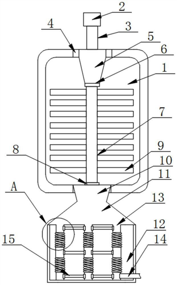
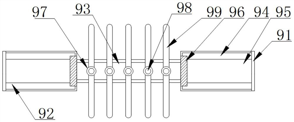
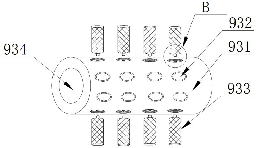
[0026] as attached Figure 1-6 A flue gas filtering and purifying device for a vacuum filter is shown, including a filter cavity 1, a control motor 2, a drive shaft 3, a flow hole 19 and a sealing sleeve 8, and the top of the filter cavity 1 is provided with a mounting hole 4, the top of the filter cavity 1 is provided with an air inlet 5, the bottom of the air inlet 5 is attached to each other with a sealing ring 6, and the bottom end of the drive shaft 3 is ...


PUM


Abstract

The invention discloses a flue gas filtering and purifying device for a vacuum filter, and particularly relates to the field of vacuum filters. The device comprises a filter cavity, a control motor, a driving shaft, a circulation hole and a sealing sleeve, wherein the top end of the filter cavity is provided with a mounting hole and an air inlet, and the bottom end of the air inlet is attached to a sealing ring. According to the invention, through the cooperation of filtering discs and filtering strips, the problems that the flue gas filtering and purifying effect is poor and the requirement of comprehensive purification cannot be met in the prior art are avoided, the filtering discs are driven to rotate at a high speed in the filter cavity, and the filtering discs are arranged in the filter cavity in batches, so that the contact area with flue gas is enlarged, the flue gas is filtered and purified more effectively, filtrate on the surfaces of the multiple filter strips interacts with the flue gas, the flue gas in the filter cavity is comprehensively purified, the purification effect is guaranteed, and the practicability of the device is improved.

Description

technical field [0001] The invention relates to the technical field of vacuum filters, more specifically, the invention relates to a flue gas filtering and purifying device for a vacuum filter. Background technique [0002] Vacuum filter is a large-scale filtering equipment capable of continuous operation. It has the outstanding characteristics of large flow, high-precision filtration, and easy automatic control. Its filtering capacity can be used for a single machine or for a certain area. It is widely used. In the fields of metallurgy, coal, sewage treatment, metal cutting, bearing manufacturing, automobile manufacturing and other fields, the current filtering equipment ranges from simple top-mounted core filters to large multi-pole filtering stations. The filtering situations are various, but there are The common problem is that it can only be used in a narrow range of small volume, small flow, and incapable of continuous work. For the emulsion circulation filtration of t...

Claims


Application Information

Patent Timeline
Patent Type & Authority Applications(China)
IPC IPC(8): B01D46/00B01D46/26B01D46/42
CPCB01D46/0056B01D46/2414B01D46/26B01D46/4218B01D46/0035B01D46/56B01D46/88
Inventor 张涛
Owner DATANG HUAIBEI POWER PLANT
Why Eureka
Try Eureka