Automatic laser cleaning system and method for traction motor of rail transit vehicle

A technology for rail transit vehicles and traction motors, which is applied in the field of laser cleaning, can solve the problems that restrict the wider application of laser cleaning technology, the shape of the shell is complex, and the dirt cannot be cleaned, so as to reduce the labor intensity of workers, improve the degree of automation, The effect of improving the cleaning effect

Inactive Publication Date: 2021-06-11
ZHUZHOU NAT INNOVATION RAILWAY TECH CO LTD
View PDF9 Cites 7 Cited by
  • Summary
  • Abstract
  • Description
  • Claims
  • Application Information

AI Technical Summary

Problems solved by technology

However, in the process of realizing automatic laser cleaning of traction motors of rail vehicles, the applicant of the patent found that there are still the following problems: ① The shape of the traction motor shell of rail vehicles is relatively complicated, and the shape of the motor shell is expressed as multiple planes and curved surfaces In the collection at different heights, if the laser scanning path is not specially designed, all the dirt on the outer surface cannot be cleaned; ② To automatically clean all the dirt on the outer surface of the traction motor at one time, the motor needs to be turned over or Displacement, how to accurately displace a motor with a weight of about 1 ton is also a problem that needs to be solved; ③Divided by vehicle type, the current area of ​​the outer surface of the traction motor is generally about 3.0-5.0m 2 , How to adopt a high-efficiency and low-cost cleaning process to ensure that the laser cleaning time of a single motor does not exceed a certain period of time (such as 20 minutes) is also a problem
[0004] To sum up, the current laser cleaning process and equipment are difficult to meet the high-efficiency and low-cost automatic laser cleaning of the traction motor housing of rail vehicles, which restricts the wider application of laser cleaning technology in the field of rail transit equipment manufacturing

Method used


Image

  • Automatic laser cleaning system and method for traction motor of rail transit vehicle

Examples


Embodiment Construction

[0033] The present invention will be further described below in conjunction with the accompanying drawings and specific embodiments.

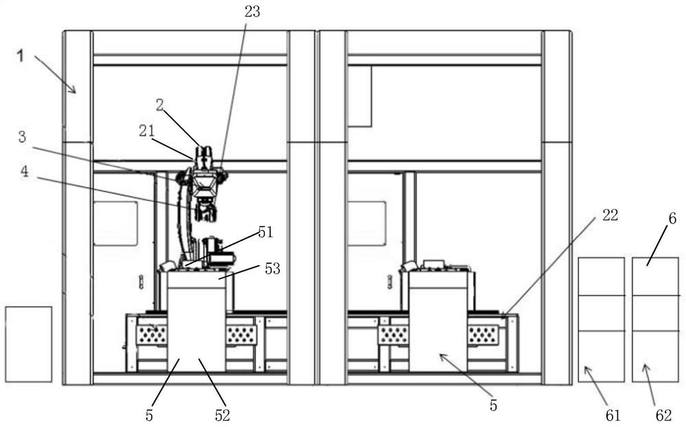
[0034] like figure 1 As shown, the automatic laser cleaning system for rail transit vehicle traction motors of the present embodiment includes a robot unit 2, a workpiece motion unit 5 and a control unit 6; the workpiece motion unit 5 is used to fix a workpiece (such as a motor) to be cleaned and Its motion, motion comprises rotation, overturn or translation etc.; Robot unit 2 comprises manipulator 21, and laser head 23 and three-dimensional scanning unit 4 (as conventional laser scanner) are installed on manipulator 21; Three-dimensional scanning unit 4, is used for motor Scan to obtain the three-dimensional shape of the motor and the area to be cleaned; the control unit 6 is connected to the three-dimensional scanning unit 4 and the laser head 23 respectively, and is used to determine the trajectory and scanning mode of the laser head 23 acco...


PUM


Abstract

The invention discloses an automatic laser cleaning system and method for a traction motor of a rail transit vehicle. The system comprises a robot unit, a workpiece moving unit and a control unit. The workpiece moving unit is used for fixing a to-be-cleaned workpiece and driving the to-be-cleaned workpiece to rotate and overturn; the robot unit comprises a manipulator, and a laser head and a three-dimensional scanning unit are mounted on the manipulator; the three-dimensional scanning unit is used for scanning the to-be-cleaned workpiece to obtain a three-dimensional shape and a to-be-cleaned area of the to-be-cleaned workpiece; the control unit is connected with the three-dimensional scanning unit and the laser head and used for determining a movement track, a scanning mode and a deflection angle in the cleaning process of the laser head according to the three-dimensional shape and the to-be-cleaned area of the to-be-cleaned workpiece; and the laser head is used for emitting laser beams and is matched with the operation of the manipulator and the overturning of the workpiece moving unit to realize automatic cleaning of the to-be-cleaned workpiece. The automatic laser cleaning system has the advantages of high automation degree, high cleaning efficiency, good cleaning effect and the like.

Description

technical field [0001] The invention mainly relates to the technical field of laser cleaning, in particular to an automatic laser cleaning system and method for traction motors of rail transit vehicles. Background technique [0002] Traction motors of rail transit vehicles need to be cleaned of dirt such as paint or oil stains on their outer surfaces during new manufacturing and maintenance. The current cleaning methods mainly include manual mechanical polishing, chemical reagent cleaning and other cleaning methods, but the above cleaning The method has problems such as harsh working environment, serious environmental pollution, long cleaning time, unclean cleaning in some places, and low degree of automation. [0003] At present, laser cleaning has the advantages of good cleaning effect, high control precision, low comprehensive cost, no consumables, no maintenance, no pollution, etc., and can also realize automatic control. It has begun to realize projects in tire mold cle...

Claims


Application Information

Patent Timeline
Patent Type & Authority Applications(China)
IPC IPC(8): B08B7/00B08B13/00
CPCB08B7/0042B08B13/00
Inventor 马明明林敏叶晨李林杨帆李泽之赵广乐肖黎亚陈皓张晶福
Owner ZHUZHOU NAT INNOVATION RAILWAY TECH CO LTD
Why Eureka
Try Eureka