
Unfired magnesia-calcium-carbon brick for preventing steel from being clamped in permanent layer of steel ladle and preparation method thereof

A technology of magnesia-calcium-carbon bricks and permanent layers, which is applied in the field of refractory materials, can solve the problems of waste of resources, early removal of refractory materials, and steel sandwiching in permanent layers, and achieve the effect of avoiding steel sandwiching in permanent layers and improving thermal shock stability

Active Publication Date: 2021-06-11
北京利尔高温材料股份有限公司
View PDF7 Cites 0 Cited by
  • Summary
  • Abstract
  • Description
  • Claims
  • Application Information

AI Technical Summary

Problems solved by technology

However, during the use of the ladle for masonry magnesia-calcium-carbon bricks, steel ladles often appear in the permanent layer, which leads to the removal of refractory materials in advance, resulting in waste of resources
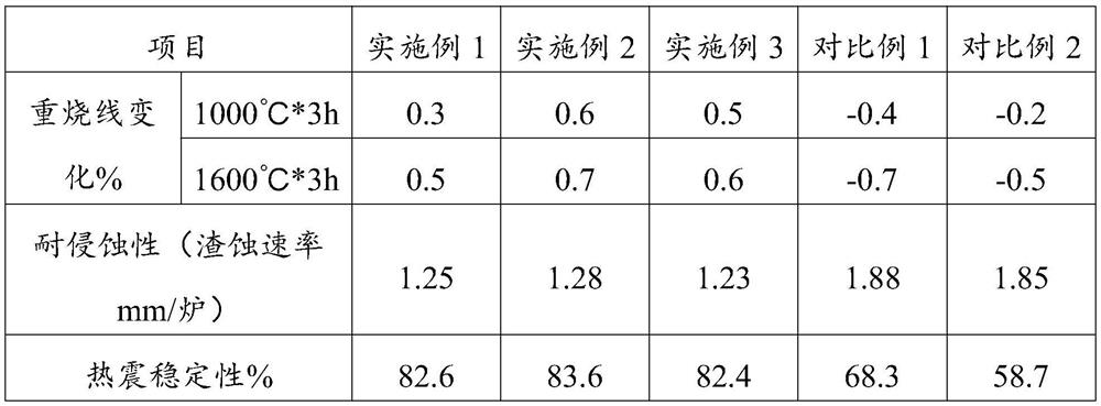
[0003] There are two main reasons for the appearance of permanent interlayer steel in the magnesia-calcium-carbon ladle: (1) When the hot ladle of the ladle is stopped for a long time or the cold ladle is not fully baked, the change of the reburning line of the magnesia-calcium-carbon brick is generally negative , so the magnesia-calcium-carbon brick masonry will have brick joints, and molten steel / slag will penetrate into the permanent layer along the brick joints, resulting in steel clamping
(2) When replacing the nozzle of the skateboard and blowing and burning the breathable brick on the hot repair platform, the magnesia-calcium-carbon brick at 12 o'clock will be displaced under the action of its own weight, and the change of the reburning line of the magnesia-calcium-carbon brick is generally negative, so The gap between the magnesia-calcium-carbon brick and the permanent layer in the 12 o'clock direction of the magnesia-calcium-carbon ladle is getting bigger and bigger, which will easily cause the permanent layer to cause steel clamping

Method used


Image

  • Unfired magnesia-calcium-carbon brick for preventing steel from being clamped in permanent layer of steel ladle and preparation method thereof

Examples


Embodiment 1

[0030] (1) Preparation of co-grinding powder: The raw material composition is: fused magnesia with a particle size of less than 0.05 mm, 320 mesh metal magnesium powder, lanthanum oxide powder with a particle size of 5 μm, titanium oxide powder with a particle size of 10 nm, and α- Alumina micropowder, 150-mesh pitch, urotropine, carbon nanotubes with a length of 25 μm and a diameter of 0.2 nm. Put into the vibrating mill for co-grinding for 10min;

[0031] (2) Take 16 parts of magnesia-calcium sand with a particle size of 3-5mm, 22 parts of magnesia-calcium sand with a particle size of 1-3mm and 3 parts of magnesia-calcium sand with a particle size of 0.05-1mm; 6 parts of fused magnesia with a particle size of 3-5mm , 3 parts of 1-3mm fused magnesia and 27 parts of 0.05-1mm fused magnesia; 0.1 part of zirconia with a particle size of 0.2mm; dry mix for 2 minutes, and then slowly add 2 parts at one time within 2 minutes with a viscosity of 8000Pa For the anhydrous phenolic re...

Embodiment 2

[0035](1) Preparation of co-grinding powder: The raw materials are composed of fused magnesia with a particle size of less than 0.05mm, 325 mesh metal magnesium powder, lanthanum oxide powder with a particle size of 55μm, titanium oxide powder with a particle size of 60nm, and α -Alumina micropowder, 170 mesh pitch, urotropine, carbon nanotubes with a length of 65 μm and a diameter of 1.4nm, and the addition ratio of each raw material is: 5:0.9:1.0:0.8:0.7:1.0:1.1:0.5. The above-mentioned raw materials were put into a vibration mill for co-grinding for 13 minutes;

[0036] (2) Take 18 parts of magnesia-calcium sand with a particle size of 3-5mm, 25 parts of magnesia-calcium sand with a particle size of 1-3mm and 5 parts of magnesia-calcium sand with a particle size of 0.05-1mm; 8 parts of fused magnesia with a particle size of 3-5mm , 5 parts of 1-3mm fused magnesia and 30 parts of 0.05-1mm fused magnesia; 1.3 parts of zirconia with a particle size of 2mm; dry mix for 2.5 minu...

Embodiment 3

[0040] (1) Co-grinding powder preparation: The raw materials are composed of fused magnesia with a particle size of less than 0.05 mm, 330 mesh metal magnesium powder, lanthanum oxide powder with a particle size of 100 μm, titanium oxide powder with a particle size of 100 nm, and α- Alumina micropowder, 200-mesh pitch, urotropine, carbon nanotubes with a length of 100 μm and a diameter of 2.5 nm, the ratio of each raw material is: 8:1.5:1.5:1.5:1.5:2:2:1, put Put into vibrating mill and grind together for 15min;

[0041] (2) Take 20 parts of magnesia-calcium sand with a particle size of 3-5mm, 28 parts of magnesia-calcium sand with a particle size of 1-3mm and 7 parts of magnesia-calcium sand with a particle size of 0.05-1mm; 10 parts of fused magnesia with a particle size of 3-5mm , 7 parts of 1-3mm fused magnesia and 33 parts of 0.05-1mm fused magnesia; 2.5 parts of zirconia with a particle size of 3mm; dry mix for 3 minutes, and then slowly add 4 parts within 2 minutes at o...


PUM

PropertyMeasurementUnit
particle sizeaaaaaaaaaa
densityaaaaaaaaaa
particle diameteraaaaaaaaaa

Abstract

The invention relates to the technical field of refractory materials, in particular to an unfired magnesia-calcium-carbon brick for preventing steel from being clamped in a permanent layer of a steel ladle. The unfired magnesia-calcium-carbon brick for preventing steel from being clamped in the permanent layer of the steel ladle is prepared from the following raw materials in parts by weight: 20-60 parts of magnesia-calcium sand, 25-75 parts of magnesia, 0.1-2.5 parts of zirconium oxide, 3-10 parts of graphite, 3-15 parts of co-grinding powder and 2-4 parts of a binding agent. By adjusting the medium / high-temperature expansion performance of the unfired magnesia-calcium-carbon brick particles and the matrix, the reheating linear change of the product at medium / high temperature is a positive value, and the situation that in the steel ladle turnover process, due to large temperature fluctuation of the magnesia-calcium-carbon working layer, gaps appear in a masonry, and steel is clamped in the permanent layer is avoided.

Description

technical field [0001] The invention relates to the technical field of refractory materials, in particular to an unfired magnesia-calcium-carbon brick that prevents steel from being sandwiched in a permanent layer of a ladle. Background technique [0002] Magnesia-calcium-carbon bricks have good high-temperature vacuum stability, thermal shock resistance, high alkalinity / acid slag erosion and penetration resistance, and liquid steel purification performance, and have a good use effect in the refining furnace outside the furnace. However, during the use of the ladle for masonry magnesia-calcium-carbon bricks, steel ladles often appear in the permanent layer, which leads to the removal of refractory materials in advance, resulting in waste of resources. [0003] There are two main reasons for the appearance of permanent interlayer steel in the magnesia-calcium-carbon ladle: (1) When the hot ladle of the ladle is stopped for a long time or the cold ladle is not fully baked, the...

Claims


Application Information

Patent Timeline
Patent Type & Authority Applications(China)
IPC IPC(8): C04B35/043
CPCC04B35/0435C04B2235/3208C04B2235/425C04B2235/3244C04B2235/401C04B2235/3227C04B2235/3232C04B2235/3217C04B2235/5288C04B2235/9615C04B2235/9669Y02P10/20
Inventor 孙春晖刘靖轩刘丽崔志强颜浩黄亚东佟晓松赵现堂张晗
Owner 北京利尔高温材料股份有限公司
Learn More