Supercharge Your Innovation With Domain-Expert AI Agents!

Over-temperature protection circuit for low-power-consumption chip

An over-temperature protection circuit, low-power technology, applied in the direction of adjusting electrical variables, control/regulating systems, instruments, etc., can solve the problems of reducing the layout area, increasing the layout area, and excessively large layout area, and achieving low power consumption Over-temperature protection and hysteresis, less circuit branches, and low overall consumption

Pending Publication Date: 2021-06-11
SUZHOU UNIV
View PDF0 Cites 1 Cited by
  • Summary
  • Abstract
  • Description
  • Claims
  • Application Information

AI Technical Summary

Problems solved by technology

[0004] However, the over-temperature protection circuit of the chip in the prior art is not suitable for low-power application environments. In low-power applications, the current must be very small. At this time, a relatively high voltage needs to be generated by flowing through a resistor. , it will inevitably require the resistance value of the resistor to become very large, then the area of ​​the layout will inevitably increase sharply
[0005] In order to solve the problem that the layout area of ​​the over-temperature protection circuit in the low-power chip will be too large if it is designed according to the existing technology, the present invention proposes a simple structure and extremely low power consumption circuit. Low, over-temperature protection circuit without resistors, greatly reducing the layout area

Method used


Image

  • Over-temperature protection circuit for low-power-consumption chip
  • Over-temperature protection circuit for low-power-consumption chip
  • Over-temperature protection circuit for low-power-consumption chip

Examples


Embodiment 1

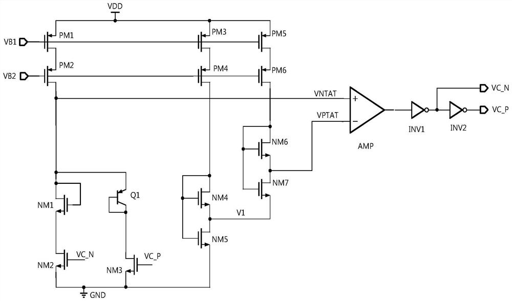
[0042] Over-temperature protection circuit for low-power chips, such as Figure 2-Figure 3 As shown, it includes: first current mirror, second current mirror, third current mirror, NMOS transistor NM1, NMOS transistor NM2, triode Q1, NMOS transistor NM3, operational amplifier AMP, NMOS transistor NM4, NMOS transistor NM5, NMOS transistor NM6 , NMOS transistor NM7, inverter INV1 and inverter INV2, the NMOS transistor NM1 is connected in series with the NMOS transistor NM2, the triode Q1 is connected in series with the NMOS transistor NM3, the NMOS transistor NM1 and the NMOS transistor NM2 are connected in parallel with the triode Q1 and the NMOS transistor NM3 It is connected in series with the first current mirror, the NMOS transistor NM4 is connected in series with the NMOS transistor NM5 and then connected in series with the second current mirror, the NMOS transistor NM6 is connected in series with the NMOS transistor NM7 and then connected in series with the third current m...


PUM


Abstract

The invention provides an over-temperature protection circuit for a low-power-consumption chip. The over-temperature protection circuit comprises a first current mirror, a second current mirror, a third current mirror, NMOS tubes NM1 and NM2, a triode Q1, NM3, an operational amplifier AMP, NMOS tubes NM4, NM5, NM6 and NM7, an inverter INV1 and an inverter INV2, the in-phase end of the operational amplifier AMP is connected with the drain electrode of the NMOS tube NM1, the anti-phase end of the operational amplifier AMP is connected with the source electrode of the NMOS tube NM6, the voltage of the in-phase end of the operational amplifier AMP is the voltage negatively correlated with the temperature, the voltage of the anti-phase end of the operational amplifier AMP is the voltage with the positive correlation of the temperature, the output end of the operational amplifier AMP is connected with the phase inverter INV1, the phase inverter INV1 is connected with the phase inverter INV2 in series, an output signal VCN of the phase inverter INV1 is transmitted to the grid electrode of the NMOS tube NM2, an output signal VCP of the phase inverter INV2 is transmitted to the grid electrode of the NMOS tube NM3, the voltage of the in-phase end of the operational amplifier AMP is compared with the voltage of the anti-phase end of the operational amplifier AMP, the output end of the operational amplifier AMP outputs a high level or a low level, so that the on-off states of the NMOS tube NM2 and the NMOS tube NM3 are changed, and the chip is controlled to work normally or is protected and closed.

Description

technical field [0001] The invention relates to the field of integrated circuit design, more specifically, to an over-temperature protection circuit for low-power consumption chips. Background technique [0002] The over-temperature protection circuit of the chip is a commonly used protection circuit that needs to be turned on all the time. If the chip continues to work in a high-temperature environment, there will be a risk of burning the internal devices of the chip, so the over-temperature protection circuit is when the temperature is too high When the temperature drops to a safe value, it provides protection action and has a certain hysteresis function, and the chip can work normally again when the temperature drops to a safe value. [0003] The traditional chip over-temperature protection circuit such as figure 1 As shown, a current that is negatively related to temperature (INTAT) is mirrored through the current mirror and flows through two resistors, thereby generati...

Claims


Application Information

Patent Timeline
Patent Type & Authority Applications(China)
IPC IPC(8): G05F3/26
CPCG05F3/262
Inventor 黄祥林李富华
Owner SUZHOU UNIV
Features
  • R&D
  • Intellectual Property
  • Life Sciences
  • Materials
  • Tech Scout
  • Unparalleled Data Quality
  • Higher Quality Content
  • 60% Fewer Hallucinations
Learn More