Pencil feeding structure of pencil sharpener

A technology for pencil sharpeners and pen feeding, which is applied in sharpening devices, printing, office supplies, etc., and can solve problems such as short service life of pen feeding components, wear blocks of pen feeding components, and broken pencil tips, etc., and achieves simple structure and low wear The effect of reducing beating and convenient processing

Pending Publication Date: 2021-06-15
温州千里目文具有限公司
View PDF0 Cites 1 Cited by
  • Summary
  • Abstract
  • Description
  • Claims
  • Application Information

AI Technical Summary

Problems solved by technology

[0003] Generally, a pencil sharpener can sharpen a pencil by turning the crank handle for about 15 to 20 turns. If the crank handle keeps turning, the pen feeding component will still drive the pencil into the reamer component, which will easily cause the tip of the pencil to break and cause unnecessary troubles;
[0004] Moreover, the pen feeding assembly of the existing pencil sharpener is too fast to send pens, and it is easy to cause waste of pencils during the pencil sharpening operation, resulting in the breakage of the pencil nib; Short life, so there are more disadvantages

Method used


Image

  • Pencil feeding structure of pencil sharpener
  • Pencil feeding structure of pencil sharpener
  • Pencil feeding structure of pencil sharpener

Examples


Embodiment 1

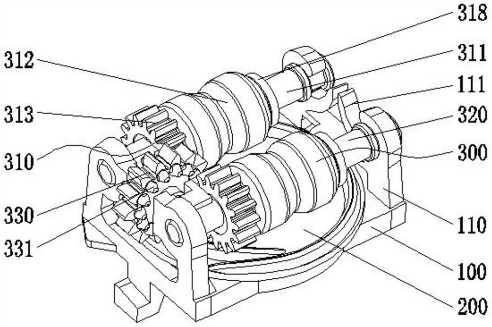
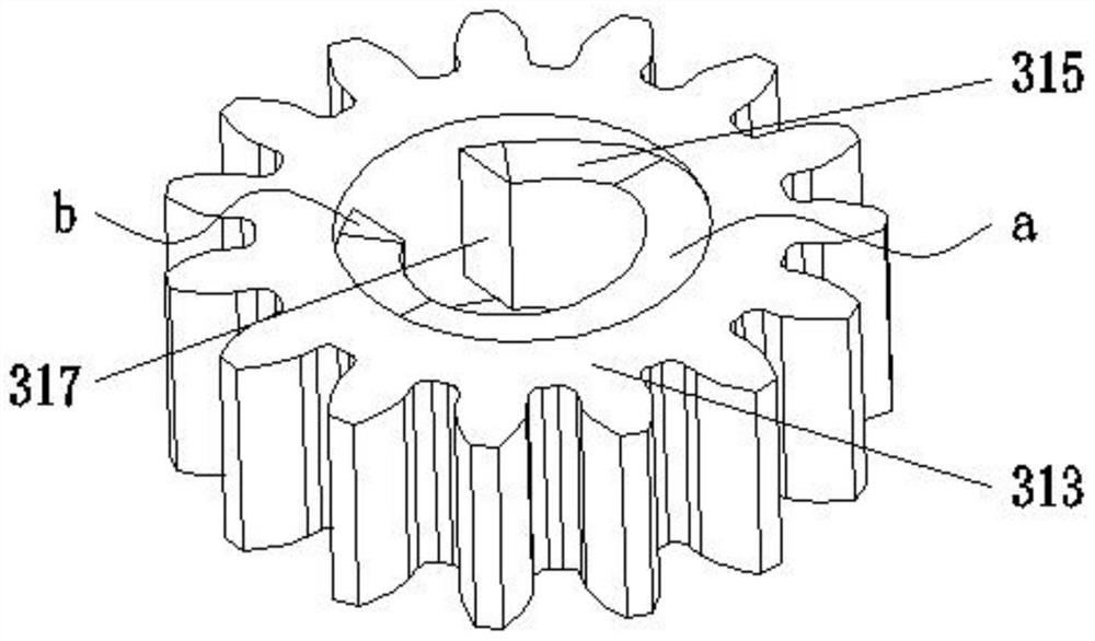
[0028] Embodiment 1: the linkage member 313 is a spur gear, the synchronous transmission member 330 is a synchronous gear, the synchronous gear is a spur gear, and the two sides of the synchronous gear are provided with convex teeth 331 for driving the spur gear to rotate. The synchronous gear is arranged at the position between the two spur gears of the installation frame 100, and the transmission is realized through gear cooperation between the driving member 200 and the pen feeding assembly 300. The teeth 331 cooperate with the linkage 313 to realize transmission.

Embodiment 2

[0029] Embodiment two, such as Figure 5 As shown, the difference between this embodiment and Embodiment 1 is that the linkage 313 is a bevel gear, the synchronous transmission 330 is a synchronous gear, the synchronous gear is a spur gear, and both sides of the synchronous gear are provided for driving The bevel gear rotates the bevel tooth 332. The synchronous gear is set at the position between the two bevel gears on the installation frame 100. The transmission principle of this embodiment is the same as that of the first embodiment, except that the synchronous gear and the linkage 313 are changed. In the meshing mode, bevel gears are used on both sides of the synchronous gear, and in the same way, the linkage 313 also uses bevel gears for meshing transmission.

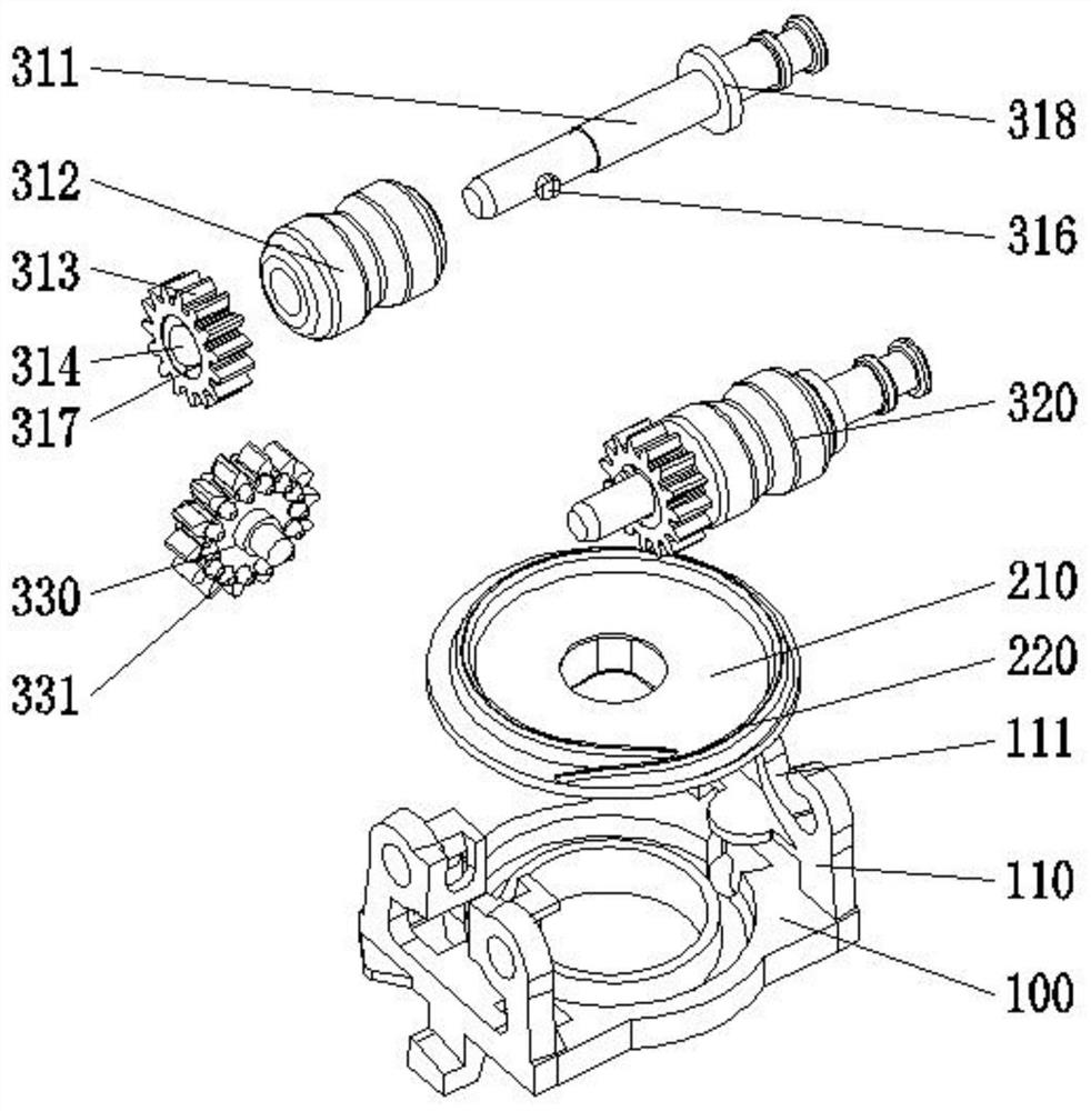
[0030] The driving member 200 includes a rotating disc 210 and a helical protrusion 220 arranged on the upper surface of the rotating disc 210. The pitch of the helical protrusion 220 is equal to the tooth pitch of...

Embodiment 3

[0031] Embodiment three; as Image 6As shown, the driving member 200 includes a rotating disc 210 and two arc-shaped protrusions 230 arranged on the upper surface of the rotating disc 210. The two arc-shaped protrusions 230 are identical in shape and arranged symmetrically. The two arc-shaped protrusions The dislocation pitch of 230 is equal to the tooth pitch of the spur gear, and the drive member 200 is engaged with the synchronous gear through the dislocated arc-shaped protrusion 230; meshing, the head end and the end of the two arc-shaped protrusions 230 are coincident in the radial angle of the rotating disk 210, and the misalignment distance between the two arc-shaped protrusions 230 is equal to the tooth pitch of the synchronous gear, thereby realizing Mesh, when the rotating disk 210 rotates half a circle, the handover of the two arc-shaped protrusions 230 is in the synchronous gear to switch a tooth position. The difference between this embodiment and the first embodi...


PUM


Abstract

The invention provides a pencil feeding structure of a pencil sharpener. A pencil feeding assembly comprises a first rotating shaft assembly and a second rotating shaft assembly, wherein the first rotating shaft assembly and the second rotating shaft assembly match and linked with a driving piece through a synchronous transmission piece, the first rotating shaft assembly comprises a rotating shaft, the pencil feeding assembly further comprises a soft pencil feeding wheel with elastic restoring force, the soft pencil feeding wheel is arranged on the rotating shaft and synchronously moves with the rotating shaft, the pencil feeding assembly further comprises a linkage piece, the linkage piece is provided with a shaft hole for allowing the rotating shaft to penetrate through, the linkage piece is arranged on one side of the rotating shaft in a sleeve mode and can rotate and axially move relative to the rotating shaft, an adjusting slope is arranged on the side wall of the shaft hole of the linkage piece, correspondingly, a radial protrusion is arranged on the side, penetrating through the linkage piece, of the rotating shaft, a gear is controlled to drive the soft pencil feeding wheel to feed a pencil or the gear to idle by changing the frictional resistance between the gear and the soft pencil feeding wheel, and therefore the problem that after a pencil is sharpened, a pencil feeding mechanism still feeds the pencil, and consequently a pencil core is broken is solved.

Description

technical field [0001] The invention relates to a pencil sharpener, in particular to a pen feeding structure of the pencil sharpener. Background technique [0002] Pencil sharpener is a relatively common office and study stationery at present. It consists of a main housing, a pen feeder assembly, a reamer assembly, a crank handle and a chip box. By turning the handle, the pencil can be sharpened quickly; [0003] Generally, a pencil sharpener can sharpen a pencil by turning the crank handle for about 15 to 20 turns. If the crank handle keeps turning, the pen feeding component will still drive the pencil into the reamer component, which will easily cause the tip of the pencil to break and cause unnecessary troubles; [0004] Moreover, the pen feeding assembly of the existing pencil sharpener is too fast to send pens, and it is easy to cause waste of pencils during the pencil sharpening operation, resulting in the breakage of the pencil nib; Short life, so there are more dis...

Claims


Application Information

Patent Timeline
Patent Type & Authority Applications(China)
IPC IPC(8): B43L23/08B43L23/04
CPCB43L23/04B43L23/08
Inventor 翁海霞潘福田潘锦泽
Owner 温州千里目文具有限公司
Why Eureka
Try Eureka