Aviation blade surface measurement method based on structured light cameras and measurement equipment

An aviation blade and structured light technology, applied in measurement devices, optical devices, image analysis, etc., can solve the problems of high measurement reliability, high measurement efficiency, large volume, etc., and meet the requirements of ensuring high quality and high performance , the effect of simplifying computational complexity and high parameter calculation accuracy

Active Publication Date: 2021-06-15
聚时科技(上海)有限公司
View PDF7 Cites 3 Cited by
  • Summary
  • Abstract
  • Description
  • Claims
  • Application Information

AI Technical Summary

Problems solved by technology

In the interior of the aero-engine, there is absolutely no slight assembly size error allowed, and the internal structure of the aero-transmitter is very complicated, and the blade is one of the parts with the worst working environment inside the engine. Continuously working for a long time, if there is an error in the design size of the blade, it is very easy to cause the blade body to be subjected to uneven cyclic stress during normal operation of the engine, resulting in the risk of fracture failure
At present, there are a series of problems in the detection of aviation blades, including: 1) The measurement accuracy is high, and the measurement accuracy of the blade surface directly affects the manufacturing accuracy of the blade
2) High measurement efficiency requirements
3) High measurement reliability requirements
However, the three-coordinate measuring machine needs to touch the surface of the object to be measured, which will inevitably cause certain damage to the blade. Moreover, the three-coordinate measuring machine has a small measurement range, large volume and is not easy to disassemble, which is greatly limited by the size of the measured workpiece. , the leaf point cloud generation speed is slow
These all bring challenges to the rapid and accurate measurement of blade parameters

Method used


Image

  • Aviation blade surface measurement method based on structured light cameras and measurement equipment
  • Aviation blade surface measurement method based on structured light cameras and measurement equipment
  • Aviation blade surface measurement method based on structured light cameras and measurement equipment

Examples


Embodiment Construction

[0048] The present invention will be described in detail below in conjunction with the accompanying drawings and specific embodiments. This embodiment is implemented on the premise of the technical solution of the present invention, and detailed implementation and specific operation process are provided, but the protection scope of the present invention is not limited to the following embodiments.

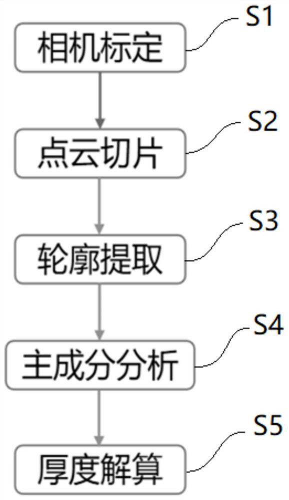
[0049] In order to ensure the high-quality and high-performance requirements of the aero-engine blades and quickly and accurately measure the dimensional parameters of the aero-engine, this invention provides a method for measuring the surface of aero-engine blades based on a structured light camera. Refer to figure 1 shown, including the following steps:

[0050] The point cloud data of the two surfaces of the aviation blade is collected by two relatively arranged structured light cameras to form a three-dimensional blade point cloud, wherein the structured light camera is calibra...


PUM


Abstract

The invention relates to an aviation blade surface measuring method based on structured light cameras and measurement equipment. The method comprises the following steps of: collecting point cloud data of two surfaces of an aviation blade through two oppositely arranged structured light cameras, and forming a three-dimensional blade point cloud; slicing the blade point cloud in the axial direction, so as to obtain section point cloud, and the axial direction being the normal vector direction of a blade section; carrying out dimension reduction on the section point cloud to a two-dimensional space; performing contour extraction on the section point cloud in the two-dimensional space to form a blade section polygon; and obtaining the maximum inscribed circle radius of the polygon of the blade section through an iterative search method, thereby obtaining the thickness of the blade. Compared with the prior art, the method improves measurement efficiency of the aviation blade while ensuring the measurement precision.

Description

technical field [0001] The invention relates to the technical field of aeroengine parameter measurement, in particular to a method and equipment for measuring the surface of an aero blade based on a structured light camera. Background technique [0002] The manufacturing level of aeroengine blades plays a vital role in engine development. At this stage, the manufacture of aero-engine blades usually cannot be processed in one step without any allowance. It is necessary to carry out a precise measurement process after the pre-processing, and the subsequent processing is further guided by the measurement results. During the repair process of engine blades, it is also necessary to measure the blades to extract the surface parameters such as the wear amount of the blades, so as to ensure the repair accuracy. Moreover, the aero-engine blade is a core component of the aero-engine, and at the same time it is a typical high-precision free-form surface part, and its precise physical ...

Claims


Application Information

Patent Timeline
Patent Type & Authority Applications(China)
IPC IPC(8): G01B11/00G01B11/06G01B11/24G01B11/255G06T3/00G06T7/80G06T17/20G06T7/62G06T7/30
CPCG01B11/002G01B11/06G01B11/24G01B11/255G06T3/0043G06T7/80G06T17/205G06T7/62G06T7/30G06T2207/10028Y02T90/00
Inventor 熊鑫鑫陈浩杨光梁天为韩建勋郑军
Owner 聚时科技(上海)有限公司
Why Eureka
Try Eureka