Separation system and separation method for oil sludge and sand

A separation system, oil sludge sand technology, applied in the direction of solid separation, wet separation, chemical instruments and methods, etc., can solve the problems of different sizes of agglomerates, difficult to be washed away, noise, etc., and achieve the effect of improving processing efficiency

Inactive Publication Date: 2021-06-18
CHINA PETROLEUM & CHEM CORP +1
View PDF15 Cites 0 Cited by
  • Summary
  • Abstract
  • Description
  • Claims
  • Application Information

AI Technical Summary

Problems solved by technology

Through experiments, the COD of the upper water in the grit chamber has increased significantly, which shows that the method involved in the patent can indeed make some organic matter fall off, but the whole process is one-time, and mud and petroleum will still adhere to the sand particles, and the separation is not complete. Disadvantages of high oil content
[0007] CN104338350A relates to an automatic cleaning device for filtering quicksand, wherein inside the sand washing chamber there are several sand washing rings with convex cross-sections. If the feeding port falls evenly at the center of the nozzle, the processing requirements can be met, but it needs to be processed The materials are usually in groups of different sizes, resulting in uneven falling, which will further cause the accumulation of materials on one side of the ring-shaped feeding port, and the phenomenon of less material on one side, requiring frequent parking and cleaning, which prolongs the processing time and increases the equipment. energy consumption
The feed port and the mud overflow port are both at the top of the device. During the opera

Method used


Image

  • Separation system and separation method for oil sludge and sand
  • Separation system and separation method for oil sludge and sand

Examples


Embodiment 1

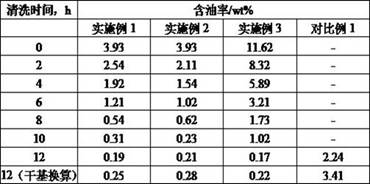
[0044] The raw materials used in this example come from the oily sludge sand separated by a three-phase separator of produced fluid in a combined station. After testing, the oily sludge sand has an oil content of 3.93wt%, a solid content of 8.21wt%, and a water content of 87.86wt% , after calculation, the oil content on dry basis is 32.37wt%.

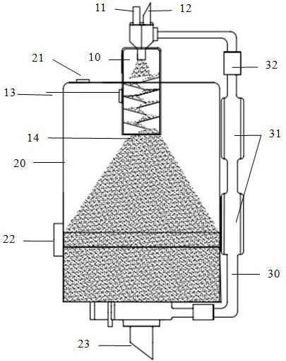
[0045] The number of built-in interlaced sand washing plates in the gas-phase sand washing zone cylinder I is 8, the downward inclination angle is 10°, the number of mixing chambers is 2, and the number of gas-phase conveyors is 2.

[0046] According to the above process, after the smooth start-up, adjust the feed flow rate of the liquid-phase sand washing zone to 2.2m 3 / h, the outlet flow of light material is 0.8m 3 / h, the working pressure of the gas phase conveyor is 0.2MPa, and the flow rate of the compressed gas introduced is 0.6m 3 / h, start timing after stable operation for a period of time. At intervals, samples are taken fro...

Embodiment 2

[0048] The raw materials used in this example are the same as those in Example 1.

[0049] The device used in Example 2, the built-in sand washing machine sand washing plate number of the cylinder body 1 is 12, and the sand washing plate is provided with some groove V-shaped grooves, and the mixing chamber number is 3, and the gas phase conveyor number is 3.

[0050] According to the above process, after the smooth start, feed into the device, and adjust the feed flow rate in the liquid-phase sand washing area to 2.8m 3 / h, the outlet flow of light material is 0.6m 3 / h, the working pressure of the gas phase conveyor is 0.35MPa, and the flow rate of the compressed gas introduced is 0.8 m 3 / h, start timing after stable operation for a period of time. At intervals, samples are taken from the interface between the sand washing channel and the cylinder I, and from the outlet of the light material. The former is used to detect the composition of the material and compare it with t...

Embodiment 3

[0052] The raw material used in this example comes from the oily mud sand in a settling tank of a joint station. After testing, its composition is 11.62wt% oil content, 52.78wt% solid content, and 35.60wt% water content. After calculation, the oil content on a dry basis is 18.04 wt%. wt%.

[0053] The device used in Example 3, the built-in sand washing machine sand washing plate number of the cylinder body 1 is 10, the mixing chamber number is 4, and the gas phase conveyor number is 4.

[0054] According to the above process, after the smooth start-up, feed into the device, and adjust the feed flow rate in the liquid-phase sand washing area to 3.3m 3 / h, the outlet flow of light material is 0.7m 3 / h, the working pressure of the gas phase conveyor is 0.6MPa, and the flow rate of the compressed gas introduced is 0.7m 3 / h, start timing after stable operation for a period of time, at intervals, take samples from the interface between the sand washing channel and the cylinder I...


PUM

PropertyMeasurementUnit
Angleaaaaaaaaaa

Abstract

The invention discloses a separation system and a separation method for oil sludge and sand. The separation system comprises a liquid phase sand washing area, a settlement area and a gas phase sand washing area, and the gas phase sand washing area comprises a gas phase sand washing channel, a plurality of mixing chambers and a gas phase conveyor. According to the separation system and the separation method, the oil sludge and the sand are thoroughly separated through reverse flushing of the oil sludge and sand materials in the liquid phase sand washing area and gas phase sand washing in the gas phase sand washing area, so that the oil content of discharged sand is low, the separation system is not liable to be blocked, and the overall energy consumption is low; and by adjusting the operating parameters of the system, the particle size composition of discharged materials can be controlled. The separation system and the separation method of the oily sludge and the sand can be widely applied to the separation process of the oil sludge and the sand.

Description

technical field [0001] The invention belongs to the technical field of environmental protection, and in particular relates to an oil sludge sand separation system and a separation method. [0002] technical background [0003] Oil mud sand refers to the mixture of mud, sand and water that is produced in oilfield production activities, mainly from various links in the crude oil gathering, transportation and processing process, and is polluted by crude oil and other organic matter. Because the hydrocarbon substances contained in the oil sludge are more harmful to the environment, they are listed in the "National Hazardous Waste List" as a hazardous waste item. At present, a large amount of oil mud sand is produced in the production process of various oil fields in the country, and its discharge has become an important factor that endangers the local environmental quality. [0004] Oil mud sand is a brown-black viscous substance with complex components, mainly composed of water...

Claims


Application Information

Patent Timeline
IPC IPC(8): B03B5/62B03B11/00B08B5/02
CPCB03B5/623B03B11/00B08B5/023
Inventor 孙浩程回军刘春阳李宝忠王宜迪
Owner CHINA PETROLEUM & CHEM CORP
Why Eureka
Try Eureka