
Rocket fairing wreckage positioning and tracking system

A positioning tracking and fairing technology, which is applied in the aerospace field, can solve the problems of poor positioning accuracy, uncertain ionospheric delay and tropospheric delay, and expand the search range, so as to improve positioning accuracy and reliability, and weaken the long baseline distance. , the effect of search work simplification

Active Publication Date: 2021-06-18
10TH RES INST OF CETC
View PDF12 Cites 2 Cited by
  • Summary
  • Abstract
  • Description
  • Claims
  • Application Information

AI Technical Summary

Problems solved by technology

Due to the long baseline distance between stations, the uncertainty of ionospheric delay and tropospheric delay caused by the weakening of correlation, and the use of Beidou short message service transmitter consumes a lot of power. In order to balance the battery power loss and short message In general, the text business is reported every tens of seconds, which is also a major reason for the poor real-time performance of this method.
If the landing area of ​​the fairing is in a mountainous area, once the last part of the fall is blocked by mountains or forests, and the communication is interrupted, it is necessary to search based on the location information of the last reported business, so the final positioning accuracy is poor, which will undoubtedly expand the search range and improve the search efficiency. difficulty

Method used


Image

  • Rocket fairing wreckage positioning and tracking system
  • Rocket fairing wreckage positioning and tracking system
  • Rocket fairing wreckage positioning and tracking system

Examples


Embodiment Construction

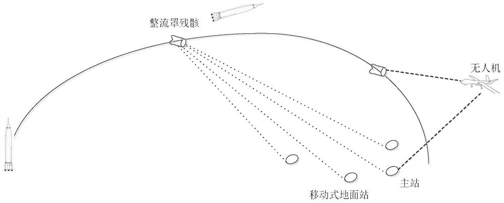
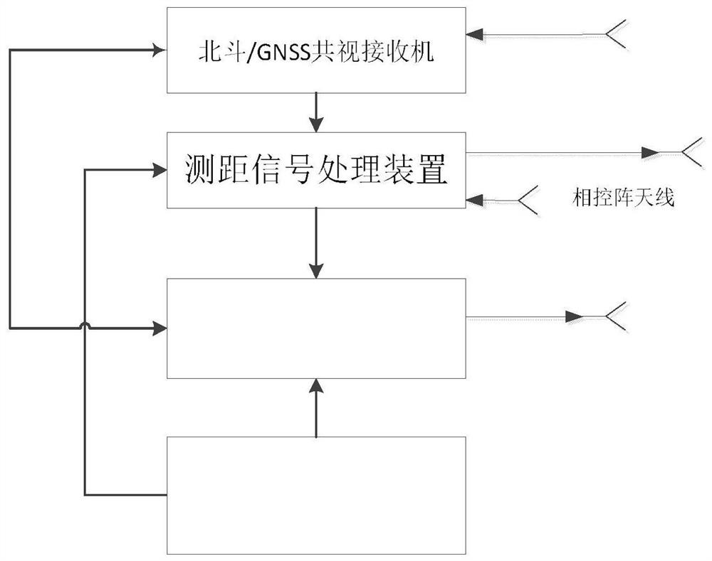
[0020] refer to figure 1. In the preferred embodiment described below, a rocket fairing wreckage positioning and tracking system includes: at least 4 mobile ground radar stations deployed on the ground, including 1 main ground radar station, at least 3 secondary stations, and mobile radar stations. The UAV that communicates with the ground radar station, and the ranging signal launcher installed in the rocket fairing, thus forming a rocket consisting of three major systems: the signal launcher installed in the fairing, the mobile ground radar station and the UAV. Fairing wreck positioning and tracking system. In locating and tracking the wreckage of the rocket fairing, the UAV obtains its own position information through its GNSS receiver, and each mobile ground radar station measures its own position information through the Beidou / GNSS common-view receiver, and realizes the inter-station time Synchronize and receive the ranging signal sent by the signal transmitter, calcula...


PUM


Abstract

The present invention discloses a rocket fairing wreckage positioning and tracking system, the problem of recovery of the rocket fairing wreckage is solved. The system is realized through the following technical scheme: each maneuvering ground radar station measures own position information through a Beidou / GNSS common-view receiver, realizes inter-station time synchronization, receives a ranging signal transmitted by a signal transmitting device, and calculates the received ranging signal to obtain the distance between the rocket fairing wreckage and a ground station; each auxiliary station reports the position information of the auxiliary station and the measured pseudo-range information of the auxiliary station and the fairing wreckage to the ground radar main station through the short-wave radio station, and the main station calculates the position coordinate of the signal transmitting device according to the position of each station and the measured pseudo-range; the azimuth and the pitch angle from the detector to the rocket fairing wreckage are calculated and transmitted to the holder; and the unmanned aerial vehicle intervenes in the falling tail section of the fairing wreckage to carry out target locking and tracking, image data are transmitted back to the ground radar master station, and the final falling point of the fairing wreckage is determined.

Description

technical field [0001] The invention relates to the aerospace field, and mainly relates to a positioning and tracking system suitable for rocket fairing wreckage. Background technique [0002] The rocket fairing is made of high-strength, lightweight, high-temperature-resistant, and radio-transparent materials. It is located on the top of the launch vehicle and protects the payload while maintaining the aerodynamic shape of the rocket. Before the rocket takes off, the fairing protects the spacecraft on the ground to ensure the requirements of the spacecraft for temperature, humidity and cleanliness. The fairing is a honeycomb half-cover structure. The half-cover weighs about 1 ton and the total weight is about 2 tons. After a period of time after launch, the first and second stages of the rocket are separated. The rocket then flew through the stratosphere and mesosphere, approaching the edge of the atmosphere. When the rocket lifts off through the atmosphere, the fairing sp...

Claims


Application Information

Patent Timeline
Patent Type & Authority Applications(China)
IPC IPC(8): G01S19/33G06T7/246G06T7/73
CPCG01S19/33G06T7/246G06T7/73G06T2207/10044Y02A90/10
Inventor 廖彦杰薛松柏龚小维叶琪玮
Owner 10TH RES INST OF CETC
Learn More