Optimal support method for fault voltage of microgrid with three-phase four-wire inverter

A three-phase four-wire system and fault voltage technology, which is applied in the direction of AC network voltage adjustment, photovoltaic power generation, single-network parallel feeding arrangement, etc., can solve the problem that cannot be realized at the same time, and the three-phase three-wire system inverter cannot output zero-sequence current , public coupling point zero-sequence voltage can not be suppressed and other issues, to achieve active power oscillation suppression maximum peak current limit, improve microgrid asymmetric fault ride-through capability, and improve the effect of control performance

Active Publication Date: 2022-05-17
HUNAN UNIV
View PDF5 Cites 0 Cited by
  • Summary
  • Abstract
  • Description
  • Claims
  • Application Information

AI Technical Summary

Problems solved by technology

[0006] The present invention provides a micro-grid fault voltage optimization support method including a three-phase four-wire inverter, which solves the problem that the three-phase three-wire grid-connected inverter in the prior art cannot Output zero-sequence current, so that the zero-sequence voltage at the point of public coupling (PCC) cannot be suppressed when a ground fault occurs in the microgrid, and the fault voltage support effect is limited; and it is impossible to simultaneously realize the optimal support of voltage at the point of public coupling (PCC) and output active power Multi-objective control problems such as oscillation suppression and peak current limitation

Method used


Image

  • Optimal support method for fault voltage of microgrid with three-phase four-wire inverter
  • Optimal support method for fault voltage of microgrid with three-phase four-wire inverter
  • Optimal support method for fault voltage of microgrid with three-phase four-wire inverter

Examples


Embodiment Construction

[0103] The following will clearly and completely describe the technical solutions in the embodiments of the present invention with reference to the accompanying drawings in the embodiments of the present invention. Obviously, the described embodiments are only some, not all, embodiments of the present invention. Based on the embodiments of the present invention, all other embodiments obtained by persons of ordinary skill in the art without making creative efforts belong to the protection scope of the present invention.

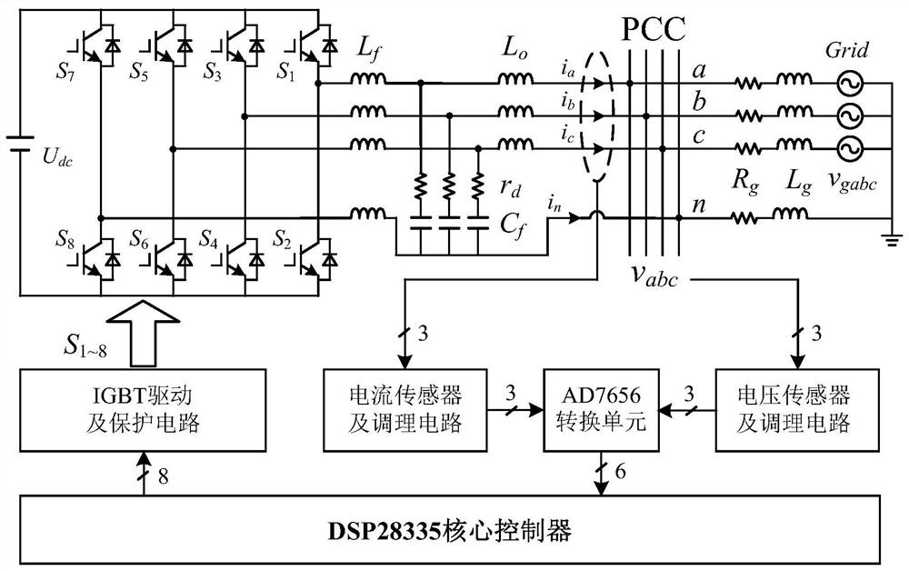
[0104] Such as figure 1 Shown is a three-phase four-wire inverter grid-connected system provided by an embodiment of the present invention, including a microgrid equivalent circuit, a three-phase four-wire grid-connected inverter main circuit, and a control system; where the three-phase The main circuit of the four-wire grid-connected inverter is electrically connected to the equivalent circuit of the microgrid at the point of common coupling (PCC), and inject...


PUM


Abstract

The invention discloses a micro-grid fault voltage optimization support method including a three-phase four-wire inverter. The method is to collect the voltage and output current at the common coupling point, obtain the voltage sequence component and the corresponding reactive voltage; obtain the αβ0 coordinate system The voltage sequence component at the lower public coupling point and the corresponding reactive voltage, the output current αβ0 coordinate system component; obtain the amplitude of each phase of the voltage at the common coupling point and compare it with the rated voltage amplitude to determine whether the microgrid is faulty; when it is determined that a fault occurs, Obtain the fault type coefficient, negative-sequence and zero-sequence voltage unbalance, and the phase difference of each sequence voltage; obtain the reference current in the αβ0 coordinate system; compare the reference current in the αβ0 coordinate system with the actual output current to generate a modulated wave voltage, and obtain the abc coordinates through inverse Clark transformation Four groups of half-bridge modules modulate the wave voltage; use the PWM module to generate four groups of half-bridge module driving signals; return and continue to perform the above steps. The method of the invention effectively improves the asymmetrical fault ride-through ability of the microgrid containing the three-phase four-wire inverter.

Description

technical field [0001] The invention belongs to the technical field of grid-connected power generation of distributed power sources, and relates to a micro-grid fault voltage optimization support method including a three-phase four-wire inverter. Background technique [0002] At this stage, as the penetration rate of distributed photovoltaic and wind power grid-connected inverters continues to increase, when common asymmetric faults such as single-phase grounding and two-phase grounding occur in low-voltage microgrids, it is easy to cause serious operational reliability problems. Based on this, relevant countries and institutions have drafted corresponding new energy grid-connected specifications, requiring that when a short-term fault occurs in the grid, the grid-connected inverter must maintain non-off-grid operation, and at the same time provide sufficient support for the fault grid voltage, that is, have fault ride-through ability. However, when the voltage of the low-v...

Claims


Application Information

Patent Timeline
Patent Type & Authority Patents(China)
IPC IPC(8): H02J3/38H02J3/12H02J3/24
CPCH02J3/38H02J3/12H02J3/24Y02E10/56
Inventor 葛俊帅智康涂春鸣冯宇赵慧敏沈霞陈燕东罗安
Owner HUNAN UNIV
Why Eureka
Try Eureka