
Electroless nickel plating solution

An electroless nickel and solution technology, applied in circuits, electrical components, electrical solid devices, etc., can solve problems such as high resistance, reduced conductivity, and non-conductivity

Active Publication Date: 2021-06-18
ATOTECH DEUT GMBH
View PDF15 Cites 0 Cited by
  • Summary
  • Abstract
  • Description
  • Claims
  • Application Information

AI Technical Summary

Problems solved by technology

This is the cause of higher resistance or reduced or even no conductivity

Method used


Image

  • Electroless nickel plating solution
  • Electroless nickel plating solution
  • Electroless nickel plating solution

Examples


Embodiment Construction

[0040] The electroless nickel plating solution of the present invention is also referred to as an electroless nickel bath or an electroless nickel plating bath. The term solution does not exclude that one or more components may be present partly in an undissolved state.

[0041] Nickel alloy layers are also referred to as quaternary nickel layers or quaternary nickel deposits, the quaternary layers comprising nickel, molybdenum, tungsten and phosphorus.

[0042] If in this description a layer is named after a metal, such as "Pd layer" or "Au layer", this term also covers alloys comprising the respective metal as a main component, if not mentioned otherwise. A major component means that the component constitutes at least 50% by weight.

[0043] When the term "comprising" is used in the present description and claims, it does not exclude other elements. For the purposes of the present invention, the term "consisting of" is considered to be a preferred embodiment of the term "c...


PUM

PropertyMeasurementUnit
thicknessaaaaaaaaaa
concentrationaaaaaaaaaa

Abstract

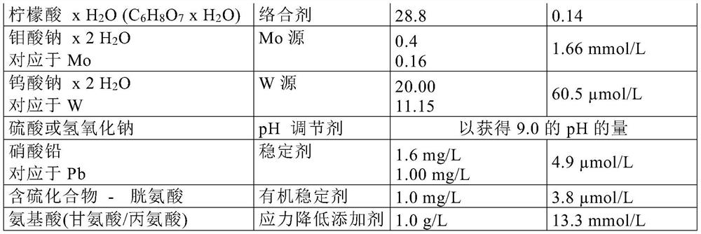
The invention relates to an electroless nickel plating solution, comprising a source of nickel ions, a source of molybdenum ions, a source of tungsten ions, a source of hypophosphite ions, at least one complexing agent, at least one organic sulphur containing compound in a concentration of 0.38-38.00 [mu]mol / L, and at least one amino acid in a concentration of 0.67-40.13 mmol / L; a method for electroless plating of a nickel alloy layer on a substrate; a nickel alloy layer and an article comprising the a nickel alloy layer.

Description

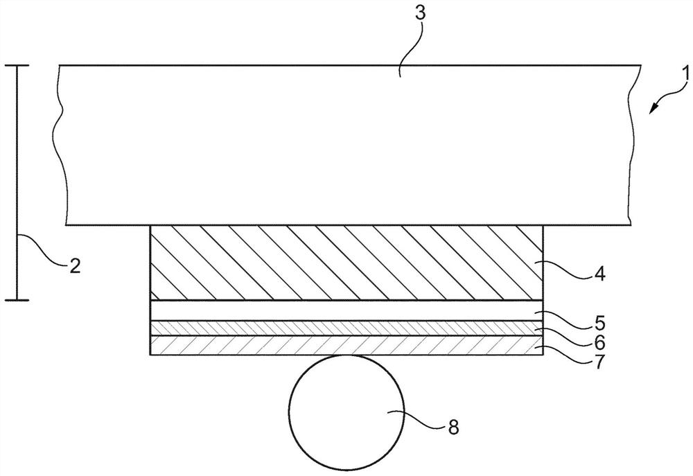
technical field [0001] The present invention relates to an electroless nickel plating solution, a method for the electroless plating of a nickel alloy layer on a substrate, a nickel alloy layer obtainable from said plating solution and a method comprising such a layer objects. Background technique [0002] Electronic objects such as semiconductor wafers or semiconductor chips often contain so-called copper redistribution layers (Cu-RDL). A redistribution layer (RDL) is an additional layer of metal that makes the input or output pads of an integrated circuit available for other locations. This makes it possible to electrically connect the chip or wafer circuit to external circuits. Typical layouts of electrical connections are bondable (solderable) connections, such as known as ball grid arrays, and pads of different geometries. In order to create a bondable (solderable) surface on the Cu-RDL, a nickel layer was plated thereon. This layer is formed for protective reasons ...

Claims


Application Information

Patent Timeline
Patent Type & Authority Applications(China)
IPC IPC(8): C22C19/03C23C18/50H01L21/288H01L23/00
CPCH01L24/03H01L24/05H01L24/13H01L24/16H01L2224/03464H01L2224/0401H01L2224/05023H01L2224/05073H01L2224/05082H01L2224/05083H01L2224/05124H01L2224/05147H01L2224/05155H01L2224/05164H01L2224/05563H01L2224/05644H01L2224/05655H01L2224/05664H01L2224/131H01L2224/16227H01L2224/94H01L2924/3512H01L2924/35121C22C19/03C23C18/50H01L2924/014H01L2924/00014H01L2224/03H01L2224/11H01L2924/01042H01L2924/01074H01L2924/01015H01L2924/013C23C18/1637C09D1/00
Inventor H·贝拉C·施瓦茨A·舒尔策
Owner ATOTECH DEUT GMBH
Learn More