Bionomic damping surface and manufacturing method thereof
A manufacturing method and sintered layer technology, applied in the field of drag reduction structures, can solve the problems of complex drag reduction effects of active drag reduction equipment, active input energy and unsatisfactory drag reduction effects, etc., to achieve wide range of applicable equipment and low manufacturing cost Low, high precision effect
- Summary
- Abstract
- Description
- Claims
- Application Information
AI Technical Summary
Problems solved by technology
Method used
Image

Examples
Embodiment 1
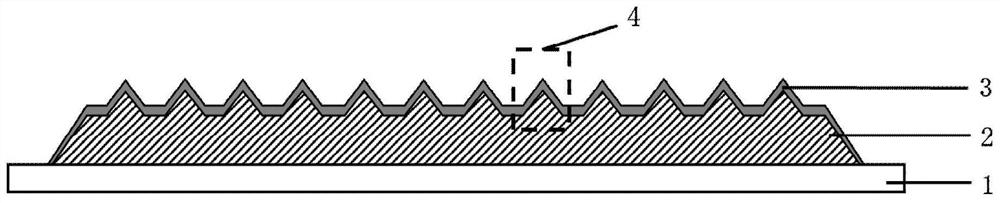
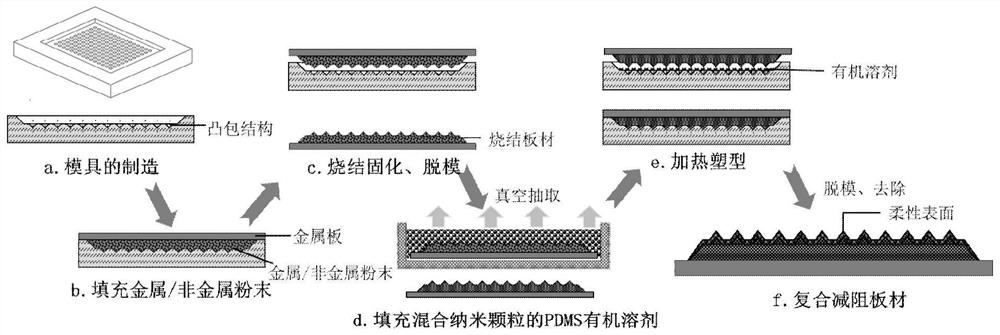
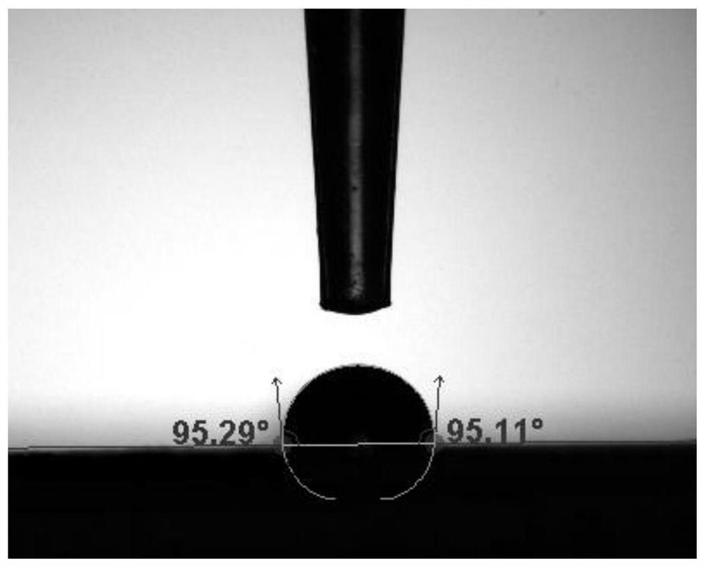
[0045] In this embodiment, a machining center is used to manufacture a graphite mold with a pit structure, which is used as a negative template for a drag-reducing / anti-fouling plate, and the nano-copper powder is sintered by a sintering process, and then PDMS / SiO is configured 2 As a filler, a composite anti-fouling / drag-reducing surface with controllable surface shape and size, flexible, hydrophobic and wear-resistant, such as figure 1 , the surface hydrophobicity test such as Figure 4 .
[0046] Step 1): use the machining center to process the template of the conical pit with a height of 0.3mm and a bottom diameter of 1mm through the steps of milling, drilling and fine grinding, and use the method of vibration and compaction to mix the nano-copper powder (50- 200nm) to fill the graphite mold, use a scraper to remove excess powder and ensure that the edge of the mold is clean. Take a metal copper sheet whose length and width are equal to the size of the mold, use an ultra...
Embodiment 2
[0051] In this example, a machining center is used to manufacture a graphite mold with a pit structure, which is used as a negative template for a drag-reducing / anti-fouling plate. The nano-copper powder / calcium carbonate is sintered into shape by a sintering process, and then PDMS / graphite powder is configured. As a filler, a composite anti-fouling / drag-reducing surface with black surface color, controllable size, flexibility, hydrophobicity and wear resistance is prepared.
[0052] Step 1): adopt the machining center to process the template of conical pits with a height of 0.3mm and a diameter of 1mm through the steps of milling, drilling and fine grinding, and configure nano-copper powder (100-200nm ) / calcium carbonate mixed powder, the mixed powder is filled into the graphite mold by vibration and compaction, the excess powder is removed by a scraper and the edge of the mold is kept clean. Take a metal copper sheet whose length and width are equal to the size of the mold, ...
Embodiment 3
[0064] In this example, a machining center is used to manufacture a graphite mold with a pit structure, which is used as a negative template for a drag-reducing / anti-fouling plate. The nano-copper powder / calcium carbonate is sintered into shape by a sintering process, and then PDMS / graphite powder is configured. As a filler, a composite anti-fouling / drag-reducing surface with black surface color, controllable size, flexibility, hydrophobicity and wear resistance is prepared.
[0065] Step 1): adopt the machining center to process the template of conical pits with a height of 0.3mm and a diameter of 1mm through the steps of milling, drilling and fine grinding, and configure nano-copper powder (100-200nm ) / calcium carbonate mixed powder, the mixed powder is filled into the graphite mold by vibration and compaction, the excess powder is removed by a scraper and the edge of the mold is kept clean. Take a metal copper sheet whose length and width are equal to the size of the mold, ...
PUM
 Abstract
Description
Claims
Application Information
 - R&D
- Intellectual Property
- Life Sciences
- Materials
- Tech Scout
- Unparalleled Data Quality
- Higher Quality Content
- 60% Fewer Hallucinations
Browse by: Latest US Patents, China's latest patents, Technical Efficacy Thesaurus, Application Domain, Technology Topic, Popular Technical Reports.
© 2025 PatSnap. All rights reserved.Legal|Privacy policy|Modern Slavery Act Transparency Statement|Sitemap|About US| Contact US: help@patsnap.com