
Engine and engineering machinery with engine

A technology of engine and transmission structure, applied in the direction of engine components, machines/engines, liquid fuel engines, etc., can solve the problems of low energy conversion efficiency of engines and hydraulic pumps, improve energy conversion efficiency, solve low energy conversion efficiency, shorten The effect of the drive chain

Active Publication Date: 2021-06-22
SANY HEAVY MACHINERY
View PDF6 Cites 0 Cited by
  • Summary
  • Abstract
  • Description
  • Claims
  • Application Information

AI Technical Summary

Problems solved by technology

[0003] Therefore, the technical problem to be solved by the present invention is to overcome the defect of low energy conversion efficiency of the engine and hydraulic pump in the prior art, thereby providing an engine and a construction machine with it

Method used


Image

  • Engine and engineering machinery with engine
  • Engine and engineering machinery with engine

Examples


Embodiment Construction

[0021] The technical solutions of the present invention will be clearly and completely described below in conjunction with the accompanying drawings. Apparently, the described embodiments are some of the embodiments of the present invention, but not all of them. Based on the embodiments of the present invention, all other embodiments obtained by persons of ordinary skill in the art without making creative efforts belong to the protection scope of the present invention.

[0022] In the description of the present invention, it should be noted that the terms "center", "upper", "lower", "left", "right", "vertical", "horizontal", "inner", "outer" etc. The indicated orientation or positional relationship is based on the orientation or positional relationship shown in the drawings, and is only for the convenience of describing the present invention and simplifying the description, rather than indicating or implying that the referred device or element must have a specific orientation, ...


PUM


Abstract

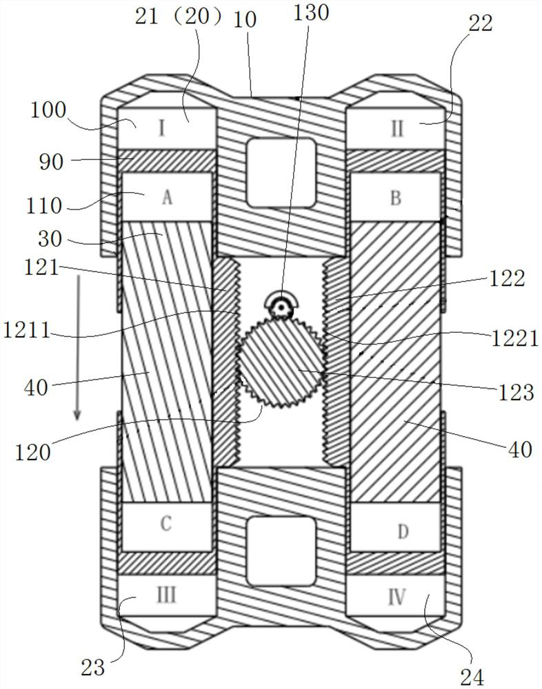
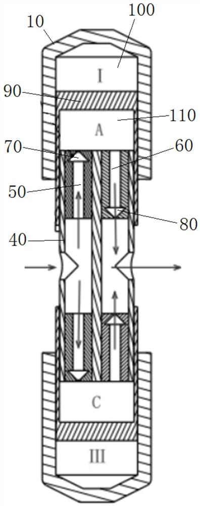
The invention provides an engine and engineering machinery with the engine. The engine comprises a cylinder body; a plurality of piston cavities, wherein the piston cavities are formed in the cylinder body, a piston is arranged in each piston cavity, a combustion chamber is defined by each piston cavity and the corresponding piston, and the pistons are suitable for reciprocating in the piston cavities; a plurality of hydraulic pump cores fixedly arranged in the cylinder body and located on the outer sides of the pistons, wherein the hydraulic pump cores and the piston cavities are arranged in a one-to-one correspondence mode, each hydraulic pump core and the corresponding piston define an oil pumping chamber, each hydraulic pump core is provided with an oil inlet channel and an oil outlet channel, and an outlet of each oil inlet channel and an inlet of the corresponding oil outlet channel both communicate with the corresponding oil pumping chamber; and a transmission structure arranged in the cylinder body and connected with the pistons, wherein the transmission structure is suitable for enabling the pistons to move in a linkage mode. According to the technical scheme, the defect that in the prior art, the energy conversion efficiency of an engine and a hydraulic pump is low is overcome.

Description

technical field [0001] The invention relates to the technical field of engineering machinery, in particular to an engine and an engineering machinery with the engine. Background technique [0002] Excavation equipment (such as excavator) is a non-road mobile machine, and the driving method of its working device is: the central shaft of the hydraulic pump (large-scale excavation equipment usually uses a plunger pump) is driven by a diesel engine to rotate, and the hydraulic pump generates oil pressure, so that the working The device provides power. In this process, the compression ignition of the engine mixture gas works on the piston, and the reciprocating motion of the piston is converted into the rotary motion of the crankshaft through the crank-link mechanism composed of the piston, connecting rod and crankshaft. The rotational motion of the crankshaft is transmitted to the central shaft of the plunger pump, which in turn makes the plunger pump work and finally generates...

Claims


Application Information

Patent Timeline
Patent Type & Authority Applications(China)
IPC IPC(8): F02B63/06F02B75/18F02B75/28F02B75/32F02F1/18F02F3/00F04B17/05F04B1/02F04B3/00F04B53/14
CPCF02B63/06F02B75/18F02B75/28F02B75/32F02F1/186F02F3/00F04B17/05F04B1/02F04B3/00F04B53/14F02B2075/1808
Inventor 王喆宋国文陈素梅
Owner SANY HEAVY MACHINERY
Learn More