Electric field pinch ion generation method and device

An ion generating device and ion generating technology, which are applied in electrostatic and electrical components, etc., can solve the problems of low ion transport efficiency, small number of ions, and reduced ion transport efficiency, etc., and achieve the effect of wide application range and simple structure.

Pending Publication Date: 2021-06-22
DALIAN UNIV OF TECH
View PDF3 Cites 0 Cited by
  • Summary
  • Abstract
  • Description
  • Claims
  • Application Information

AI Technical Summary

Problems solved by technology

And the ion generator of needle-mesh structure form is that the high-voltage output end of high-voltage power supply 3 is connected with the high-voltage electrode needle, and the low-voltage output end of high-voltage power supply 3 is connected with the low-voltage electrode mesh and then grounded, or the low-voltage output of high-voltage power supply 3 The end and the low-voltage electrode mesh are respectively grounded. Most of the ions generated by the ion generator with this structure are collected by the low-voltage electrode mesh, and only a part of the remaining ions are sent out through the low-voltage electrode mesh. Therefore, the ion generator of this type Ion transport efficiency is low
The ion generator in the form of needle structure is that the high-voltage output end of the high-voltage power supply 3 is connected with the high-voltage electrode needle, and corona discharge is generated around the high-voltage electrode needle, and the ions are transported out under the action of the electric field force and the carrier gas. Low-voltage grid electrode, so the structure is simple, but because the electric force lines of the needle electrode 1 are divergent, the number of ions transported in a direction is small, and the efficiency of ion transport is also reduced.

Method used


Image

  • Electric field pinch ion generation method and device
  • Electric field pinch ion generation method and device
  • Electric field pinch ion generation method and device

Examples


Embodiment Construction

[0033] An embodiment of the present invention will be described below with reference to the drawings.

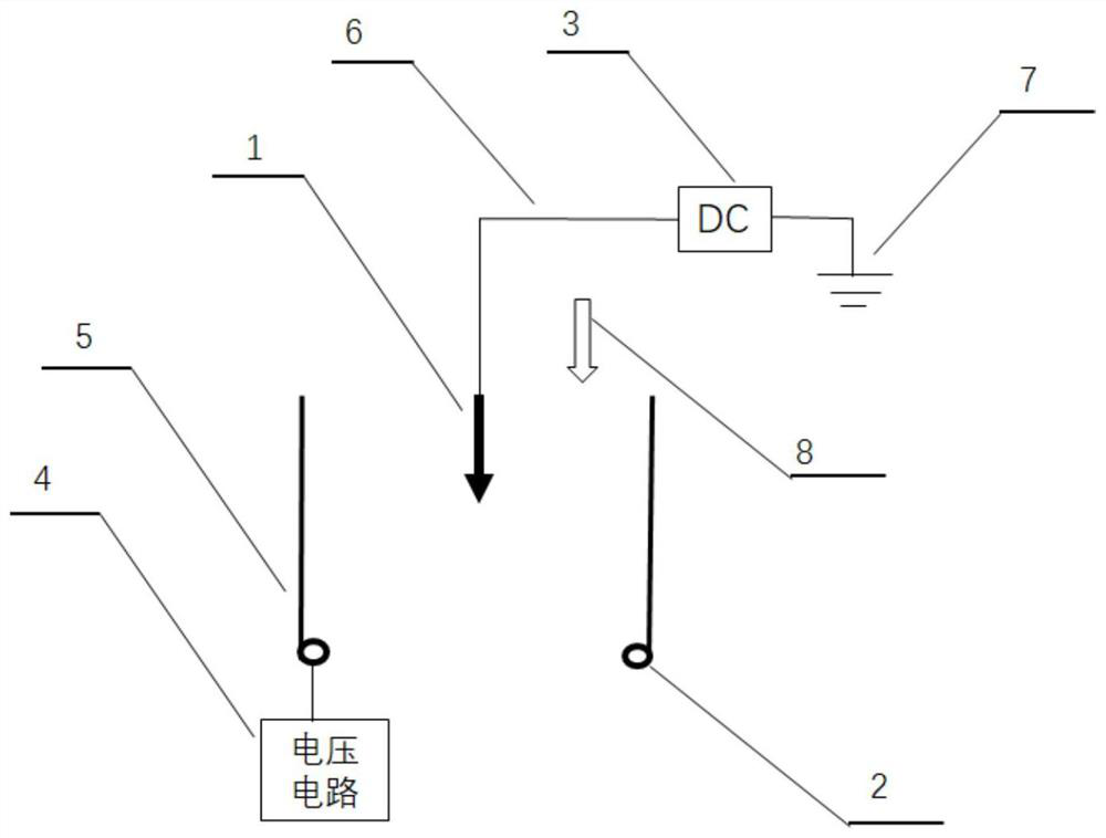
[0034] Described a kind of electric field pinching ion generating device is made up of needle electrode 1, ring electrode 2, high-voltage power supply 3, voltage circuit 4, trachea 5 etc., and needle electrode 1 and ring electrode 2 are coaxially placed in the polyethylene of inner diameter 20mm On the central axis of the trachea 5, the ring electrode 2 is located on the edge of the mouth of the trachea 5. The needle electrode 1 is a stainless steel needle with a diameter of 1.3 mm and a needle tip angle of 15 degrees. The ring electrode 2 is a ring with an outer diameter of 20 mm made of a stainless steel wire with a diameter of 1.5 mm. , the distance between the tip of the needle electrode 1 and the ring electrode 2 is 10mm, the output end of the high-voltage power supply 3 is connected to the needle electrode 1 through a wire 6, and the airflow 8 is introduced through the ...


PUM


Abstract

The invention provides an electric field pinch ion generation method and device aiming at the problem of less ion output of a power supply ion generator, and belongs to the industries and fields of electrostatic application and electrostatic prevention of petrochemical engineering, environmental protection, microelectronics, textile and the like. The device is composed of a needle electrode and a ring electrode, the needle electrode is placed on the central axis of the geometric center of the ring electrode, the potential polarity of the needle electrode and the potential polarity of the ring electrode are the same, ions generated by corona discharge of the needle electrode fly to the ring electrode under the action of electric field force, and due to the fact that the potential of the ring electrode is the same as the polarity of the ions, the ions fly to the ring electrode. Ions generated by corona discharge are pinched into ion beams to penetrate through the ring electrode to be output, and directional efficient output of the ion generator is achieved. The ion generation device has the beneficial effects that the structure is simple, ions are efficiently generated in an energy-saving manner, and the ion generation device can be applied to an ion injection or injection process in industry and enterprise production.

Description

technical field [0001] The invention relates to a method and device for generating electric field pinch ions, which belong to industries and fields of static electricity application and antistatic such as petrochemical industry, environmental protection, microelectronics, and textiles. Background technique [0002] Many insulating materials are used in the production process of petrochemical, microelectronics and textile industries. These insulating materials basically exist in the form of gas, liquid or solid (powder, particle or surface), and when these insulating materials Or generate static electricity through contact (collision or friction) with the conductor, so that the surface of the material has accumulated charges to form an electric field. On the one hand, under the action of the electric field, the insulating material attracts surrounding fine substances, such as dust, or attracts charges with different signs. As a result, the industry cannot run stably or the qu...

Claims


Application Information

Patent Timeline
Patent Type & Authority Applications(China)
IPC IPC(8): H01T23/00H05F3/04
CPCH01T23/00H05F3/04
Inventor 李杰王凌晨姜楠
Owner DALIAN UNIV OF TECH
Why Eureka
Try Eureka