Efficient mineral exploitation equipment
A mineral and high-efficiency technology, applied in the direction of filter screen, grille, using liquid separating agent, etc., can solve the problems of difficult transportation, different fineness, low utilization rate in the later period, etc., to improve crushing efficiency, ensure fineness, improve The effect of efficiency
- Summary
- Abstract
- Description
- Claims
- Application Information
AI Technical Summary
Problems solved by technology
Method used
Image

Examples
Embodiment 1
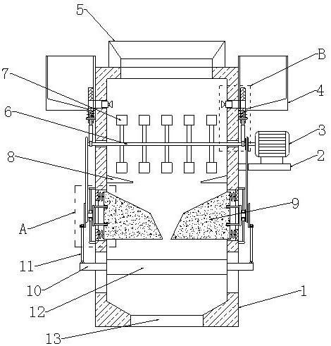
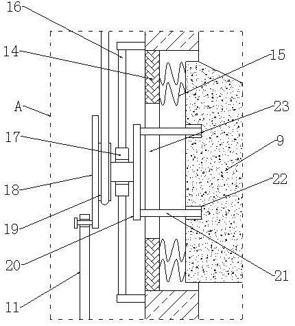
[0030] refer to Figure 1-5 , a high-efficiency mineral mining equipment, including a housing 1, a mounting plate 2 is fixedly installed on one side of the housing 1, and a driving motor 3 is fixedly installed on the top of the mounting plate 2, and the output shaft of the driving motor 3 is fixedly connected to a rotating rod 6, and the rotating rod 6 traverses through the housing 1, the end of the rotating rod 6 away from the drive motor 3 and the rod body are fixedly connected with the main pulley 32, and the rotating rod 6 is fixedly connected with multiple structures on the rod body inside the housing 1 For the same breaking hammer 7, the two sides of the housing 1 are provided with symmetrically distributed installation grooves, and the broken pieces 9 are slidably installed in the installation grooves, and the outer side of the installation groove is fixedly installed with a baffle 14, and the baffle 14 is connected with the broken pieces. 9 is connected with a first re...
Embodiment 2
[0034] refer to Figure 1-3 as well as Figure 5 and Figure 6A sieve plate 12 is slidably installed inside the housing 1, and the sieve plate 12 is located below the broken block 9, and both sides of the sieve plate 12 are fixedly connected with movable plates 10, and the movable plates 10 extend to the outside of the housing 1, and Its top is spherically connected with a connecting rod 11, and both sides of the housing 1 are provided with movable grooves, and the movable grooves are matched with the movable plate 10, and the side of the secondary pulley 19 away from the limit plate 17 is fixedly connected with a turntable 18, and the turntable 18 is hinged to the top of connecting rod 11 on one side away from secondary pulley 19, and the hinge point is close to the edge position of rotating disk 18.
[0035] On the basis of Embodiment 1, this embodiment adds the step of screening the crushed ore. During the rotation of the secondary pulley 19, it will drive the turntable 1...
Embodiment 3
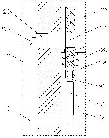
[0037] refer to figure 1 , image 3 and Figure 5 , two symmetrically distributed cams 31 are fixedly sleeved on the rod body of the rotating rod 6, and the two cams 31 are arranged on both sides of the housing 1, and the water tank 4 is fixedly installed on both sides of the housing 1, and the water tank 4 Located above the cam 31, the lower part of the side where the casing 1 and the water tank 4 are close to each other is provided with a water inlet connected to each other, and a water collection pipe 24 is installed at the water inlet, and a plurality of nozzles with the same structure are evenly installed on the water collection pipe 24 25, and the spray head 25 is set towards the inside of the housing 1.
[0038] The bottom end of the water tank 4 slides through and is provided with a leak-proof plate 26, and the leak-proof plate 26 is fixedly sleeved with a fixed plate 29 on the plate body below the water tank 4, and the top of the fixed plate 29 is fixedly connected ...
PUM
 Abstract
Description
Claims
Application Information
 - R&D
- Intellectual Property
- Life Sciences
- Materials
- Tech Scout
- Unparalleled Data Quality
- Higher Quality Content
- 60% Fewer Hallucinations
Browse by: Latest US Patents, China's latest patents, Technical Efficacy Thesaurus, Application Domain, Technology Topic, Popular Technical Reports.
© 2025 PatSnap. All rights reserved.Legal|Privacy policy|Modern Slavery Act Transparency Statement|Sitemap|About US| Contact US: help@patsnap.com