

Encapsulation method for silicon-based flat micro heat pipe
A flat-plate micro-heat pipe and silicon substrate technology, which is applied in the process of producing decorative surface effects, micro-structure technology, and micro-structure devices, etc. The effect of spot flow and curing enhancements, facilitating integrated manufacturing applications, improving results
- Summary
- Abstract
- Description
- Claims
- Application Information
AI Technical Summary
Problems solved by technology
Method used
Image

Examples
Embodiment 1
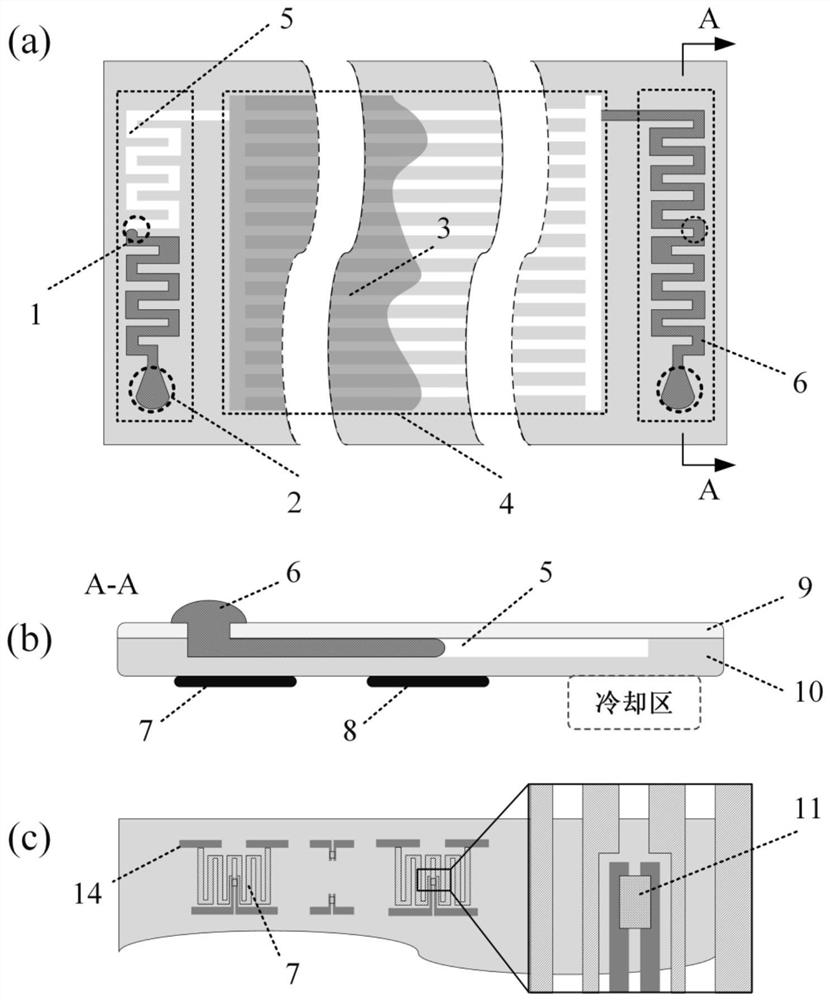
[0041] combine Figure 1-2 , the silicon-based flat micro-heat pipe includes a sealed channel area and a micro-groove area, the sealed channel area is arranged on both sides of the micro-groove area, and a micro-groove group is arranged inside the micro-groove; An opening leading to the sealing channel area; the sealing channel area is provided with a sealing channel, and the sealing channel is provided with a working fluid injection / exhaust hole and an alloy injection hole, and the sealing channel has a continuous "bow" structure with one end and The microgroove group is connected, and the alloy injection port is set at the end of the sealing channel, and the working medium injection / extraction hole is set at the middle of the sealing channel.
[0042] The main film heater is set at the lower side of the working fluid injection / extraction hole, and the auxiliary film heater is set at the lower side of the alloy injection hole; both the main film heater and the auxiliary film ...
Embodiment 2
[0045] Pretreatment of silicon substrates:
[0046] In order to prevent internal air bubbles during sealing, the silicon substrate needs to be pretreated to improve its bonding performance with the low melting point alloy; the pretreatment method includes the following steps:
[0047] Step 1. Processing of the silicon substrate: the silicon substrate is formed by forming microgrooves on the silicon wafer by means of laser or chemical etching;
[0048] Step 2. Place the silicon substrate and the glass cover plate in an ultrasonic cleaning machine for cleaning with ultrapure water, acetone, alcohol, and ultrapure water. The cleaning time is 10 to 20 minutes for each solvent, and the cleaning temperature is 30 to 50°C;
[0049] Step 3: Carry out graphical modeling of the sealed channel area on the silicon substrate in the computer, and form a graph of the area to be treated by laser in the computer; then process the cleaned silicon substrate and glass cover under the action of fe...
Embodiment 3
[0056] combine Figure 1-2 , the first step is to make them respectively through MEMS processing technology:
[0057] 1) a silicon substrate 10 with a film main heater 7, a film auxiliary heater 8, a microgroove group 4 and a sealed channel 5;
[0058] 2) A glass cover plate 9 with a working fluid injection / exhaust hole 1 and an alloy injection hole 2. And seal the silicon substrate 10 and the glass cover 9 by electrostatic bonding;
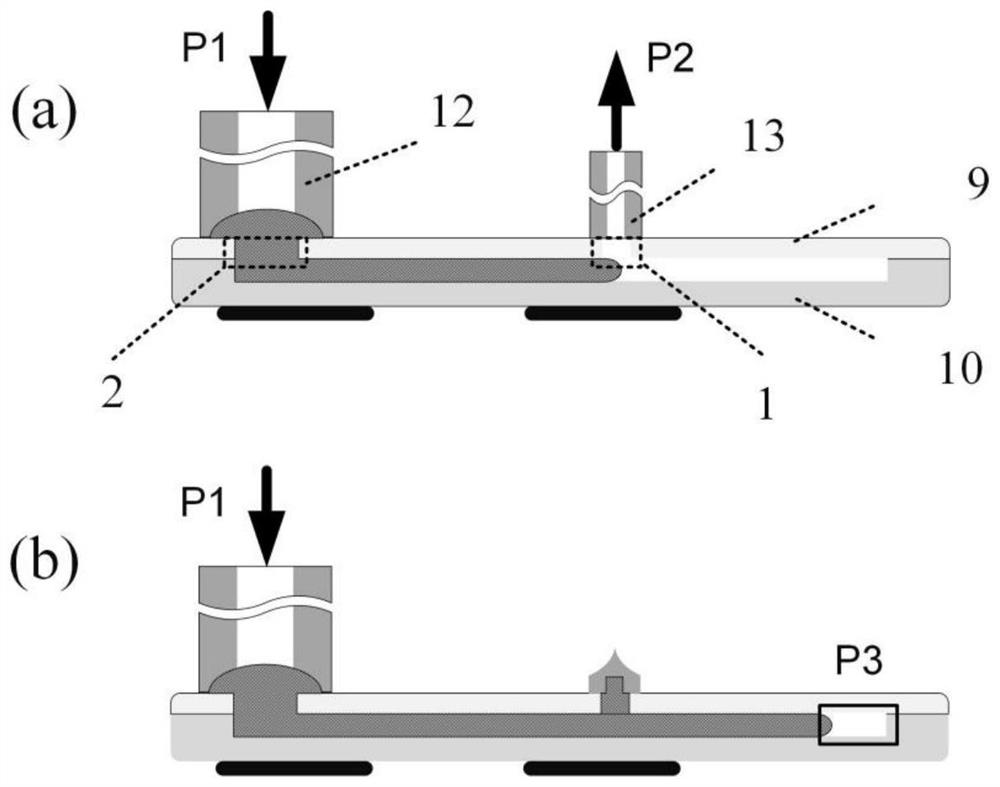
[0059] In the second step, on both sides of the sealing channel 5, use sealant to bond the copper tube to the working fluid injection / extraction hole 1 and the alloy injection hole 2;
[0060] The third step is to place a sufficient amount of low-melting point alloy 6 (melting point is 139°C) at the alloy injection hole 1, control the temperature of the film heater 7 to be 145°C and the temperature of the film heater 8 to be 130°C, and use a small controllable air pump to make the A pressure difference of 50kPa is formed between the copper tub...
PUM
| Property | Measurement | Unit |
|---|---|---|
| Depth | aaaaa | aaaaa |
Abstract
Description
Claims
Application Information