
Combined type airflow jetting device suitable for powder materials

An air jet and combined technology, which is applied in the direction of furnace components, transportation and packaging, lighting and heating equipment, etc., can solve the problems of long storage time, increasing the vibration force and vibration time of the air vibrator, and easy bridging of powder, etc. Achieve the effect of easy installation or disassembly, improve feeding efficiency and save production cost

Pending Publication Date: 2021-06-25
CNNC JIANZHONG NUCLEAR FUEL
View PDF0 Cites 0 Cited by
  • Summary
  • Abstract
  • Description
  • Claims
  • Application Information

AI Technical Summary

Problems solved by technology

[0004] Since the waste uranium-containing powder comes from various links of the uranium chemical production line and powder metallurgy production line, it has the characteristics of high impurity content, long storage time, extremely irregular particle shape, and rough surface, resulting in extremely poor fluidity of the powder
The performance characteristic in the hopper is that the powder is easy to bridge and difficult to enter the spiral, even if the vibration intensity and vibration time of the air vibrator are increased, it will not help
The difficulty of feeding makes the production of the entire oxidation and calcination process difficult, far below the design level

Method used


Image

  • Combined type airflow jetting device suitable for powder materials
  • Combined type airflow jetting device suitable for powder materials
  • Combined type airflow jetting device suitable for powder materials

Examples


Embodiment Construction

[0024] The present invention will be further described below by means of the accompanying drawings and specific embodiments.

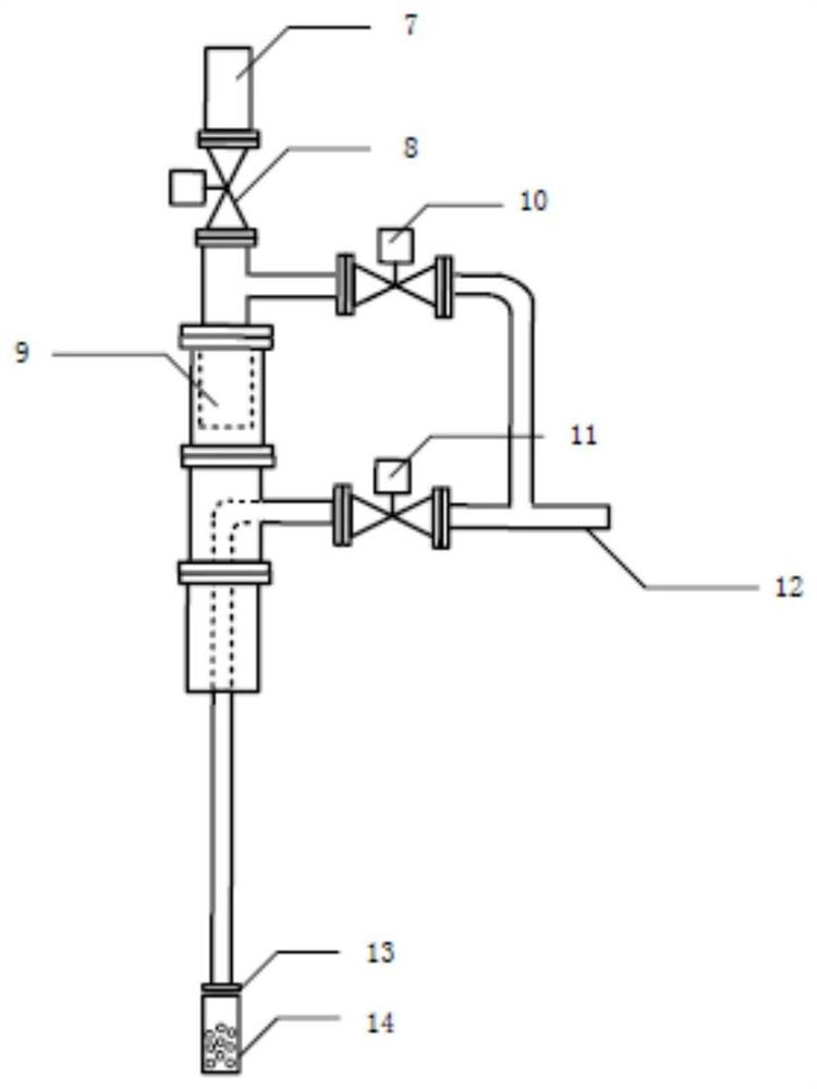
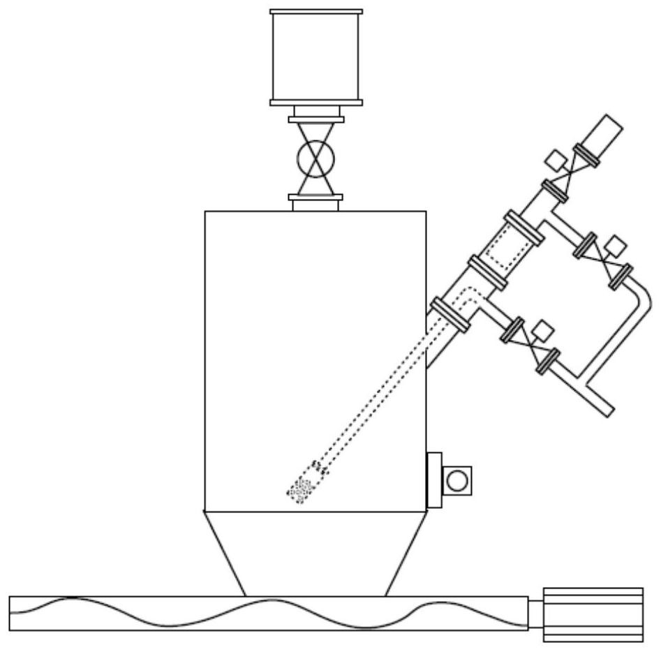
[0025] Such as figure 1 As shown, the combined airflow injection device suitable for powder materials includes a vent pipe 7, a vent solenoid valve 8, an air intake pipe 12, a filter pipe 9, an injection pipe 16, an air outlet pipe 15, a filter pipe purge solenoid valve 10, an air jet Solenoid valve 11 and spray head 14.

[0026] The uppermost one is an emptying pipeline 7, and an emptying solenoid valve 8 is installed at its lower end, and the emptying electromagnetic valve 8 is connected with an air inlet pipe 12, and the air inlet pipe 12 has two air inlets.

[0027] The filter pipe 9 is installed above the injection pipe 16, the top opening of the filter pipe 9, the side opening of the injection pipe 16, and the air intake pipe 12 has two air inlets to connect the upper end opening of the filter pipe 9 and the injection pipe 16 through the air int...


PUM


Abstract

The invention belongs to the fields of nuclear chemical engineering and powder metallurgy, and particularly relates to a combined type airflow jetting device suitable for powder materials. The device comprises an emptying pipeline at the uppermost part, an air inlet pipeline connected to the emptying pipeline through an emptying electromagnetic valve, a filter pipe and an injection pipe which are respectively communicated with two air inlets of the air inlet pipeline, an air outlet pipe arranged below the injection pipe, and an injector head arranged at the lower end of the air outlet pipe, wherein the filter pipe is located above the injection pipe, an opening is formed in the upper portion of the filter pipe, an opening is formed in the side face of the injection pipe, and the two air inlets of the air inlet pipeline are connected to the opening in the upper end of the filter pipe and the opening in the side face of the injection pipe through the air inlet pipeline respectively. According to the device, the flow ability of the powder can be effectively improved, the feeding efficiency of the powder is improved, and the remarkable benefits of improving the production efficiency of a material returning production line and saving the production cost are achieved. The device is convenient to install or remove, the injector head and the injection pipe are in a separable mode, and the injector head can be made into various modes to meet various different application occasions.

Description

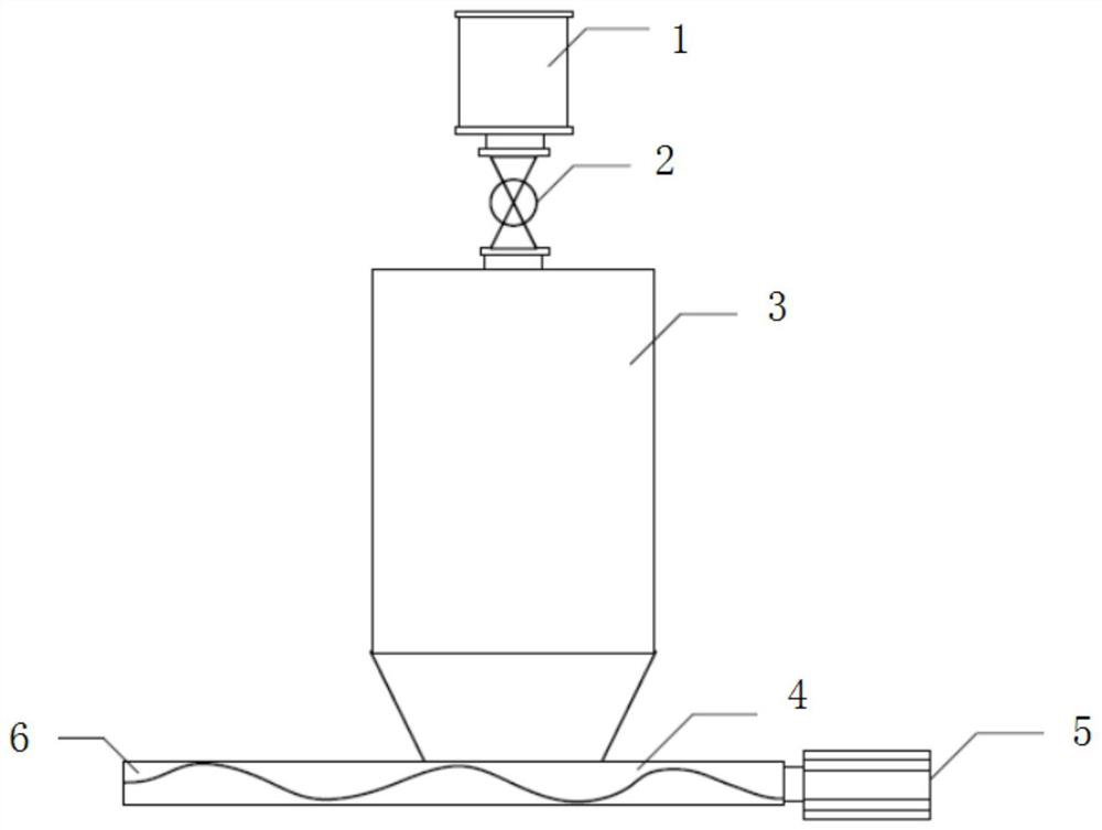
technical field [0001] The invention belongs to the fields of nuclear chemical industry and powder metallurgy, and in particular relates to a combined airflow injection device suitable for powder materials. Background technique [0002] The return line for the recycling and production of waste uranium-containing powder is an important link in the nuclear fuel production cycle. The return line includes calcination, dissolution, extraction, precipitation, drying, reduction, stabilization, homogenization and other processes, and the waste uranium-containing powder is converted into uranium dioxide powder that meets the requirements for pellet preparation. Various waste uranium-containing powders must first be oxidized and calcined in a rotary calciner to produce U3O8 powder, and then sent to the subsequent nitric acid dissolution post for processing. [0003] The feed system of the original design oxidation calcination process see figure 1 As shown, the feeding device of the ...

Claims


Application Information

Patent Timeline
Patent Type & Authority Applications(China)
IPC IPC(8): F27D3/16B22F9/16B22F1/00
CPCF27D3/16B22F9/16F27D2003/168B22F1/145
Inventor 王建卫高春英
Owner CNNC JIANZHONG NUCLEAR FUEL
Learn More