High-precision real-time three-dimensional measurement system and method for measuring micro defects on surface of aviation component

A real-time three-dimensional, measurement system technology, applied in the direction of optical testing flaws/defects, measuring devices, and material analysis through optical means, can solve problems such as integrability, poor portability, large number of components, and complex systems, etc., to achieve Good beam stability, good imaging effect, and simple system

Pending Publication Date: 2021-06-25
AIR FORCE UNIV PLA
View PDF21 Cites 2 Cited by
  • Summary
  • Abstract
  • Description
  • Claims
  • Application Information

AI Technical Summary

Problems solved by technology

[0006] In order to solve the shortcomings of the existing dynamic polarization phase-shifting interferometry technology system, which has a large number of components, a complex system, and poor integration and portability for aerospace parts detection, the present invention provides a high-precision real-time three-dimensional Measurement system and method

Method used


Image

  • High-precision real-time three-dimensional measurement system and method for measuring micro defects on surface of aviation component
  • High-precision real-time three-dimensional measurement system and method for measuring micro defects on surface of aviation component

Examples


Embodiment Construction

[0032] Embodiments of the present invention are described in detail below, and the embodiments are exemplary and intended to explain the present invention, but should not be construed as limiting the present invention.

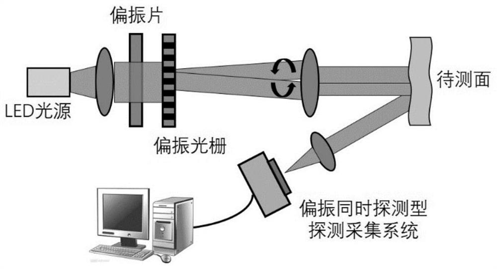
[0033] Such as figure 1 As shown, the structure schematic diagram of the high-precision real-time three-dimensional measurement system for measuring micro-defects on the surface of aerospace components of the present invention includes a light source system, a polarized light modulation subsystem, a target to be measured, a detection and acquisition system, and a computer processing system.

[0034] The light source system can select the wavelength according to the material of the detection component. The detection component is a metal material as an example, and the light source adopts a 450nm blue LED.

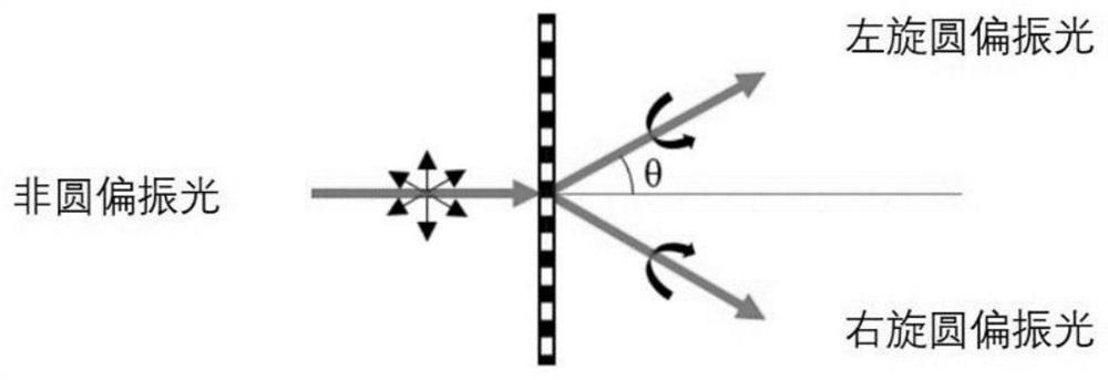
[0035] The polarization modulation subsystem includes two parts: a beam collimation component and a polarization state modulation component arranged sequent...


PUM


Abstract

The invention provides a high-precision real-time three-dimensional measurement system and method for measuring micro defects on the surface of an aviation component. The system comprises a light source system, a polarized light modulation subsystem, a to-be-measured target, a detection and acquisition system and a computer processing system which are sequentially arranged along a light path; the polarized light modulation subsystem comprises a light beam collimation assembly and a polarization state modulation assembly which are sequentially arranged along the light path. Modulation of two beams of circularly polarized light with opposite rotation directions is realized by adopting the polarization grating, and the system is simple, compact and convenient to integrate and carry; according to the invention, a focal plane type polarization detector is adopted, four polarization images can be obtained at the same time, images under four phase shifts can be obtained through single exposure, and the three-dimensional shape of the surface defect of a to-be-detected part is solved in real time; by means of the polarized light imaging, light beam stability is good, accuracy is high, strong reflection flare light on the surface of a component can be effectively eliminated, and the imaging effect is better.

Description

technical field [0001] The invention belongs to the field of non-destructive testing in the aviation industry, and relates to a system and method for high-precision and real-time measurement of the three-dimensional appearance of micro-defects on the surface of aviation components. Background technique [0002] During the long-term working process, the aircraft is affected by various factors such as airflow erosion, high-temperature oxidation, and mechanical wear, and it is easy to produce micro-defects on the surface, such as surface scratches, cracks, oxidation corrosion of various coatings, and surface peeling off. , These early micro-defects are easy to expand under the action of high temperature and high pressure, high-speed airflow erosion, and heavy load, forming irreparable macro cracks and defects, causing component failure and scrapping, and seriously affecting flight safety. [0003] At present, the detection of surface defects of most components on the front line...

Claims


Application Information

Patent Timeline
Patent Type & Authority Applications(China)
IPC IPC(8): G01N21/01G01N21/95
CPCG01N21/01G01N21/95
Inventor 汪诚巨海娟丁相玉王强吴静李卓越安志斌
Owner AIR FORCE UNIV PLA
Why Eureka
Try Eureka