Terahertz time-domain spectroscopy system and step length adaptive adjustment method thereof

A terahertz time-domain, adaptive adjustment technology, applied in the field of terahertz spectroscopy and imaging, can solve problems such as complex calculations, strong dependence, and small amount of scanning data

Active Publication Date: 2021-07-06
青岛青源峰达太赫兹科技有限公司
View PDF11 Cites 1 Cited by
  • Summary
  • Abstract
  • Description
  • Claims
  • Application Information

AI Technical Summary

Problems solved by technology

The characteristic peak width of common substances is only less than 1 ps. If the step size is forcibly increased, the number of acquisition points and time consumption will be reduced, but the amount of scanning data for the characteristic peak part is too small to accurately present its time-domain spectral characteristics.
The whole system relies heavily on the external computer 7, and cannot even work without an external computer for process control. At the same time, because of the need for more complex calculations, it also has certain requirements for the computing power of the external computer.

Method used


Image

  • Terahertz time-domain spectroscopy system and step length adaptive adjustment method thereof
  • Terahertz time-domain spectroscopy system and step length adaptive adjustment method thereof
  • Terahertz time-domain spectroscopy system and step length adaptive adjustment method thereof

Examples


Embodiment 1

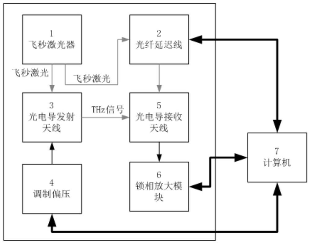
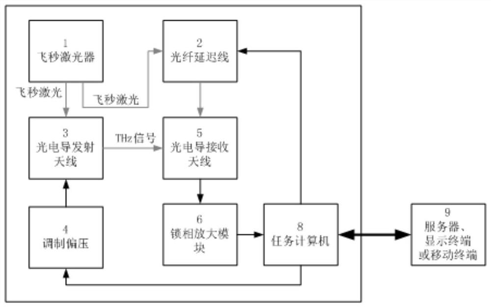
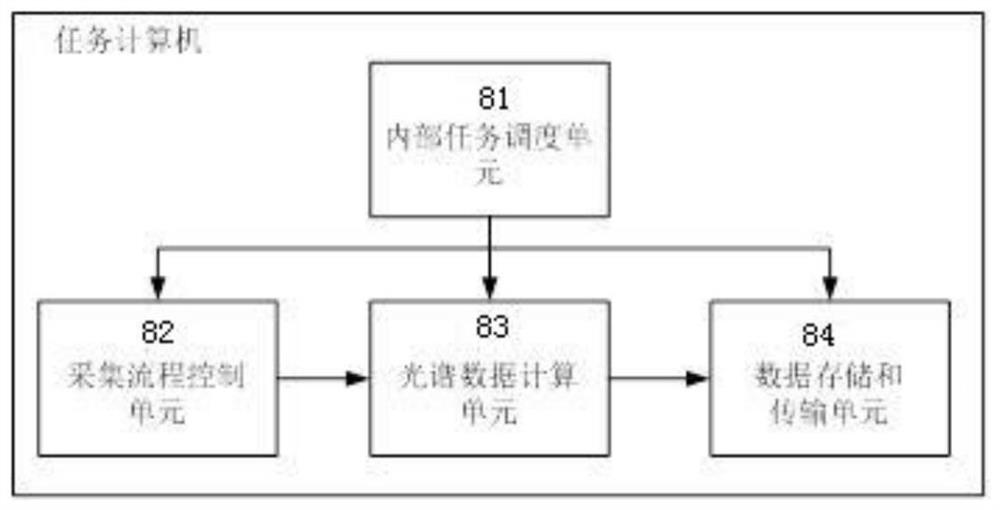
[0033] Such as figure 1As shown, a high-precision terahertz time-domain spectroscopy system based on a mission computer includes a femtosecond laser 1, a fiber delay line 2, a photoconductive transmitting antenna 3, a bias source 4, a photoconductive receiving antenna 5, and a lock-in amplifier 6 And task computer 8, femtosecond laser 1 is connected with photoconductive transmitting antenna 3, bias source 4 is connected with photoconductive transmitting antenna 3, femtosecond laser 1 is connected with photoconductive receiving antenna 5 through optical fiber delay line 2, photoconductive receiving antenna 5 is connected with the lock-in amplifier 6, and the task computer 8 is connected with the fiber delay line 2, the bias source 4 and the lock-in amplifier 6 respectively, and the task computer 8 includes an internal task scheduling unit 81, an acquisition process control unit 82, and spectral data calculation Unit 83 and data storage and transmission unit 84, wherein, the int...

Embodiment 2

[0036] For this reason, this embodiment adopts an adaptive variable step size method, which significantly shortens the scanning time while ensuring the accuracy of feature data collection, thereby improving detection efficiency. As in the above example, a scan step of 0.2 ps is used outside the characteristic peak data area, and a scan step of 0.01 ps is used in the area where the characteristic peak appears. Reduced, and the time resolution of the feature area has also increased by a factor of 1.

[0037] As an implementation, such as Figure 4 As shown, a terahertz time-domain spectrum adaptive variable step adjustment method, the specific steps are as follows:

[0038] (A1) Starting from the initial delay value ds, control the fiber delay line to start scanning according to a fixed step;

[0039] (A2) The time-domain waveform of the terahertz spectrum is identified, and the slope of the period t is calculated as kt=(At-At-1) / dt-1, where At is the delay measurement value a...


PUM


Abstract

The invention discloses a terahertz time-domain spectroscopy system step length adaptive adjustment method which comprises the following steps: (1) starting from an initial delay value ds, controlling an optical fiber delay line to start scanning according to a fixed step length; and (2) identifying the obtained terahertz spectrum time domain waveform, judging (or predicting) whether the terahertz spectrum time domain waveform belongs to a characteristic peak value data region, if so, setting the step length of the next step as a smaller step length, otherwise, setting the step length of the next step as a larger step length. The self-adaptive variable step length method is adopted, so that the scanning time is obviously shortened while the feature data acquisition precision is ensured, and the detection efficiency is improved. Meanwhile, the invention discloses a terahertz time-domain spectroscopy system based on a task computer, the dependence on an external computer in the spectral measurement process is relieved, the requirement for the computing performance of the computer is reduced, and the expandability of the system is enhanced.

Description

Technical field: [0001] The invention belongs to the technical field of terahertz spectroscopy and imaging, and in particular relates to a method for adaptively adjusting the step size of a terahertz time-domain spectroscopy system. Background technique: [0002] Such as figure 1 As shown, the terahertz time-domain spectroscopy system includes a femtosecond laser 1, a fiber delay line 2, a photoconductive transmitting antenna 3, a bias source 4, a photoconductive receiving antenna 5, a lock-in amplifier 6, and a computer (host computer) 7. First, Femtosecond laser 1 generates femtosecond laser 1 into sub-beams, one beam is pump light, and the other beam is probe light. Under the action of bias voltage source 4, the pump light is irradiated on THz photoconductive transmitting antenna 3 to form Photogenerated free carriers, when the terahertz pulse and the probe light irradiate the electrode gap of the THz photoconductive receiving antenna 5 at the same time, the femtosecond ...

Claims


Application Information

Patent Timeline
IPC IPC(8): G01J3/12G01J3/28G01J3/02
CPCG01J3/12G01J3/2823G01J3/0218G01J2003/2826
Inventor 朱新勇初文怡刘虎张朝惠刘永利王博
Owner 青岛青源峰达太赫兹科技有限公司
Why Eureka
Try Eureka