Laser melting deposition forming ultrasonic workbench

A laser melting deposition, workbench technology, applied in the direction of additive processing, process efficiency improvement, energy efficiency improvement, etc., can solve problems such as mechanical anisotropy of materials, reduce residual stress, improve various properties, fine The effect of crystallizing

Active Publication Date: 2021-07-09
HARBIN INST OF TECH
View PDF19 Cites 0 Cited by
  • Summary
  • Abstract
  • Description
  • Claims
  • Application Information

AI Technical Summary

Problems solved by technology

[0004] In order to solve the problem of obvious anisotropy in the mechanical properties of the material due to the formation of a large number of oriented columnar cryst

Method used


Image

  • Laser melting deposition forming ultrasonic workbench
  • Laser melting deposition forming ultrasonic workbench
  • Laser melting deposition forming ultrasonic workbench

Examples


Example Embodiment

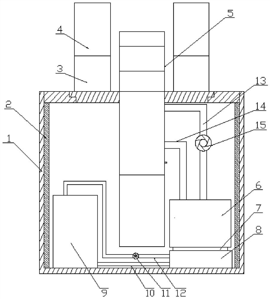
[0015] Specific Embodiment 1: In this embodiment, the laser melting deposition forming ultrasonic workbench is composed of a workbench box 1, several infrared heaters 4, several lifting platforms 3 and ultrasonic vibrators 5;

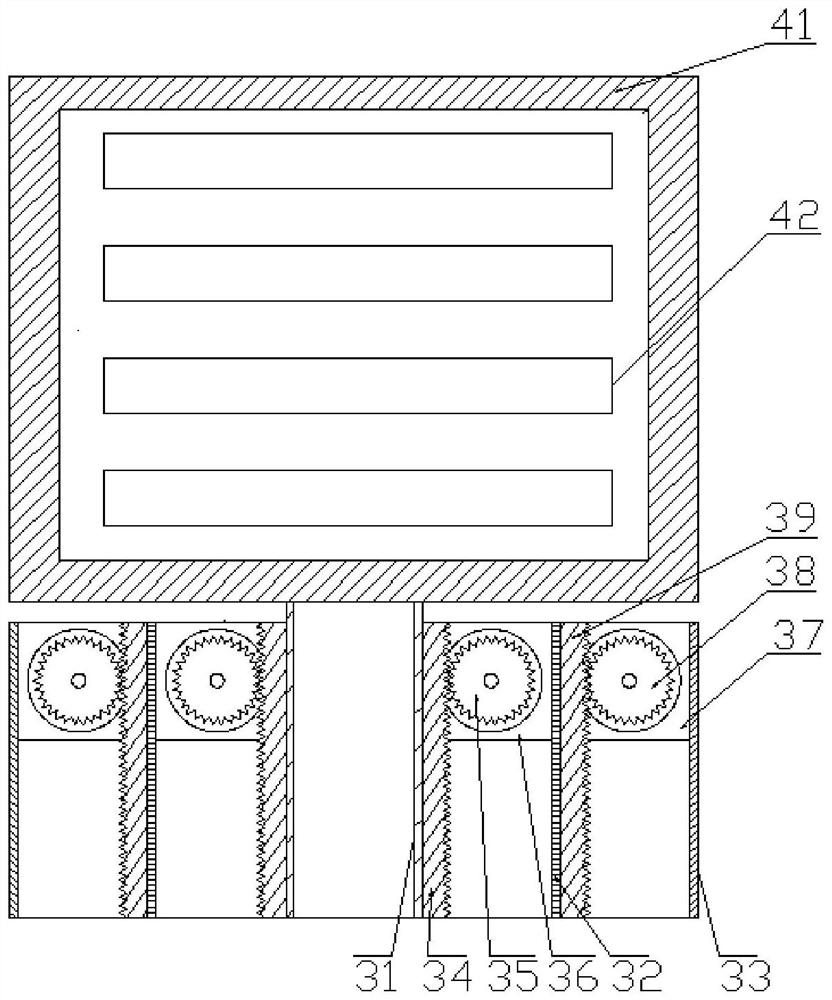
[0016] The lifting platform 3 is composed of an inner cylinder 31, a middle cylinder 32 and an outer cylinder 33. The inner cylinder 31, the middle cylinder 32 and the outer cylinder 33 are all rectangular cylinders. The inner cylinder 31 is arranged in the middle cylinder 32, and the middle cylinder 32 is arranged in the outer cylinder 33. Inside; the inner wall of the middle cylinder 32 is fixedly connected with two symmetrically arranged first stepper motors 36, the power output shaft of the first stepper motor 36 is provided with a first gear 35, and the outer wall of the inner cylinder 31 is provided with two symmetrical The vertical first rack 34, the first gear 35 meshes with the first rack 34, the inner wall of the outer cylinder 33 is fixedly co...

Example Embodiment

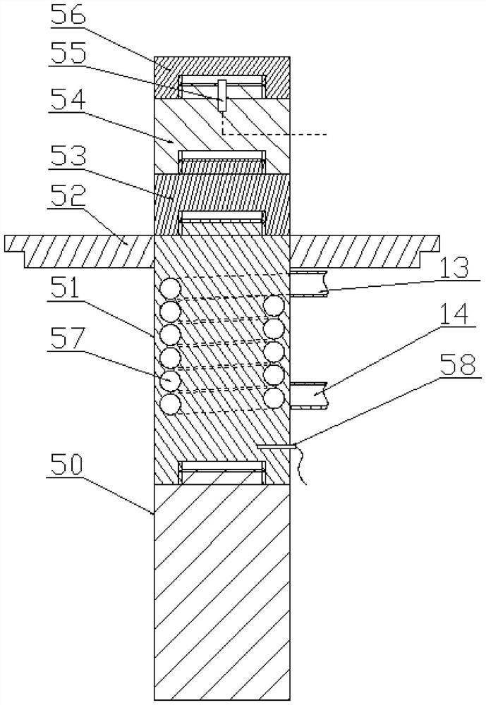
[0019] Specific embodiment two: the difference between this embodiment and specific embodiment one is: the two end faces of the first gear 35 and the two end faces of the second gear 38 are respectively provided with positioning baffles 30, and the positioning baffles 30 is circular, and the outer diameter of the positioning baffle 30 is greater than the outer diameters of the first gear 35 and the second gear 38 .

Example Embodiment

[0020] Embodiment 3: This embodiment is different from Embodiment 1 or 2 in that: the plurality of infrared heating tubes 42 are arranged in a vertical array.


PUM


Abstract

The invention relates to a laser melting deposition forming ultrasonic workbench, in particular to a laser melting deposition forming ultrasonic workbench. The purpose is to solve the problem of mechanical property anisotropy of metal materials prepared through a laser melting deposition method. The workbench consists of a workbench box body, a plurality of infrared heaters, a plurality of lifting tables and ultrasonic vibrators; a first cooling water tank, a semiconductor chilling plate, a cooling plate and a second cooling water tank are arranged in the workbench box body, and each lifting table is provided with an infrared heater. According to the method, a columnar solidification structure in the laser melting deposition process is broken through high-strength ultrasound, and the anisotropic characteristic of the material performance is reduced. Meanwhile, a liftable infrared heating tube is adopted to heat a substrate and a deposition material in real time, the temperature gradient in the material in the forming process is reduced, the residual stress in the formed material is reduced, and the mechanical property of the material is improved. The laser melting deposition forming ultrasonic workbench is suitable for metal material laser melting deposition forming.

Description

technical field [0001] The invention relates to a laser melting deposition forming ultrasonic workbench. Background technique [0002] As an advanced metal material forming method, laser melting deposition technology uses metal powder as the raw material, and uses a special nozzle to spray the high-energy laser beam and metal powder on the surface of the forming substrate synchronously. The metal powder is melted, and the molten metal powder spreads and solidifies on the surface of the forming substrate. During this process, the nozzle moves at a certain speed according to the preset scanning path under the control of the computer, and the forming of the metal part can be completed. However, there are a large number of elongated columnar crystals along the construction direction inside the metal material formed by the laser melting deposition method. These oriented columnar crystals make the metal material show a strong texture phenomenon, and the mechanical properties of th...

Claims


Application Information

Patent Timeline
IPC IPC(8): B22F3/105B22F12/30B22F12/10B22F12/00B33Y30/00B33Y40/00
CPCB22F3/003B22F3/105B33Y30/00B33Y40/00B22F2202/00Y02P10/25
Inventor 黄永江赵文杰吕云卓胡伟华陆毅李红革宁志良姜思达孙剑飞
Owner HARBIN INST OF TECH
Why Eureka
Try Eureka